I have a problem with the initial cut point, can someone help?
I see you have ZigZagRamp selected for the Entry type. The link below illustrates that pattern. Did you try Plunge entry?
Actually, I was about to post something related to start point when I saw this. I’m finding that when I set the start point far away from where MillMage sets it by default, that when exporting the GCode to run via gSender that MillMage seems to ignore my new set start points. Is this by design or doing something wrong?
I looked for that in the MillMage DOCs, but could not find it. Do you mind sharing it?
Can you share about the first 15 lines of the GCode file, including where you expected the start point to be?
Hi,
Sharing? I don’t have anything from documents. I was using the tool and saw where the bit insertion is occuring so I added a node where I wanted the cut to begin. I placed the insertion on the vector I included the first few Gcode lines at the bottom line or, more/less a rectangle. The bottom edge will be covered so I decided to make the beginning there. It seems the beginning by default is very near a curve. Something else that may be important - I did this design using Adobe Illustrator and saved as an SVG then importing that SVG into MillMage eventually making toolpaths.
On the imported design and tool paths is where I tried adding the node and putting the starting point.
Here are the first few lines
;MillMage Core 0.8.00-RC-14 @ e747243 Qt6.5.7
;Custom GCode device profile, absolute coords
;Bounds: X14.633 Y14.795 to X417.167 Y290.004
;Project Units: Metric
;Safe Retract = 50.8
;Stock Thickness: 5.08
;Z Zero: Top
;Workpiece origin is at the Bottom Left
G00 G17 G40 G21;Restore metric mode
G54
G90;Restore absolute mode
G0 Z50.8
G90;Restore absolute mode
;01 - 1/8 Comp - Rough Profile Out (0.02 Stock) @ 599.44 mm/min, 10000 RPMs
M5
T0
M3 S10000
G0 Z50.8
G0 X142.842Y14.803Z50.8
G0 Z1
G1 Z0F119.89
G1 X142.713Y14.795Z-0.054
G1 X139.01Z-1.587
G1 X142.713Z-3.121
G1 X142.842Y14.803Z-3.175
G1 X142.713Y14.795F599.44
G1 X88.586
G1 Z-2.667
G1 X80.429
G1 Z-3.175F119.89
G1 X15.713F599.44
G1 X15.576Y14.804
G1 X15.449Y14.828
G1 X15.325Y14.868
G1 X15.207Y14.921
G1 X15.096Y14.989
G1 X14.994Y15.069
G1 X14.903Y15.162
G1 X14.823Y15.264
G1 X14.756Y15.375
G1 X14.703Y15.494
G1 X14.665Y15.618
G1 X14.641Y15.746
G1 X14.633Y15.875
G1 Y157.302
G1 Z-2.667
G1 Y165.458
G1 Z-3.175F119.89
G1 Y282.575F599.44
G1 Y282.629
G1 X14.667Y283.278
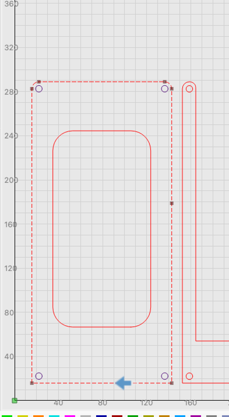
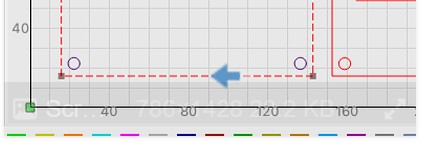
I’m unsure how to show where I want the starting point to be. But its in the bottom of the rectangle. Ah, here is a partial screenshot. There is an arrow at the bottom line of the outer rectangle. I appreciate any ideas.
Thanks
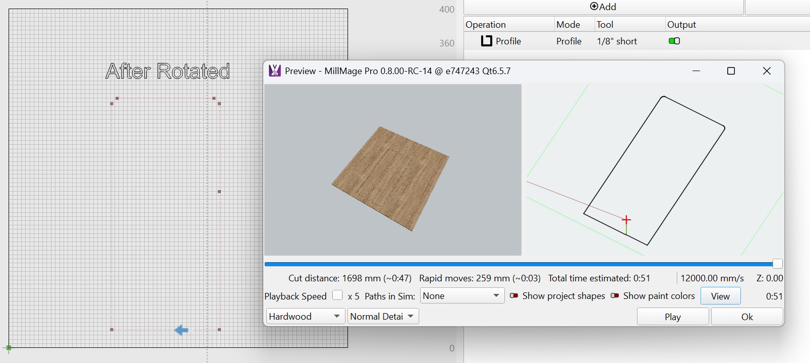
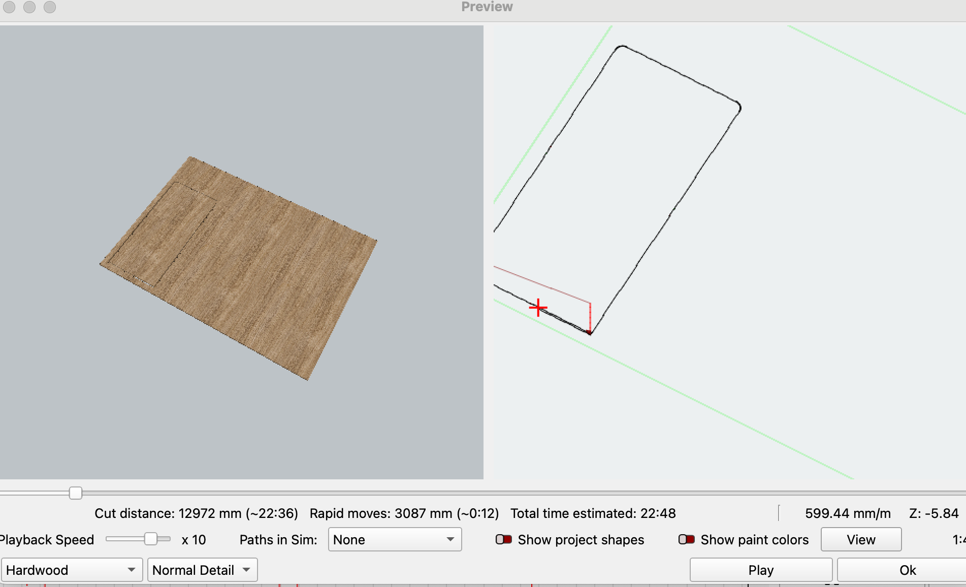
Something else I just thought of. Perhaps a screenshot of the Preview will help. Interestingly, the preview shows the starting point NOT where I manually placed it but where MM places the starting by default.

Here is the preview running more so its clear to see the corners of the rectangle and where the insertiong point it. The insertion point is clear NOT where I told it to - or atleast thought I told it.
You did not describe how you did this. I could find nothing in the DOCs explaining hoe to control the starting (feed into the part) point.
Can you upload both the .mage and .nc files we are working with here? I am seeing some moves in the GCode that is not making sense based on the image provided.
Hi
1 Like
Have no idea why I could not find that. Thanks!
In your image, I do not see a node at the location of the blue arrow. MillMage need a Node at that point. Did you insert one there before trying to assign it as a Start Point?
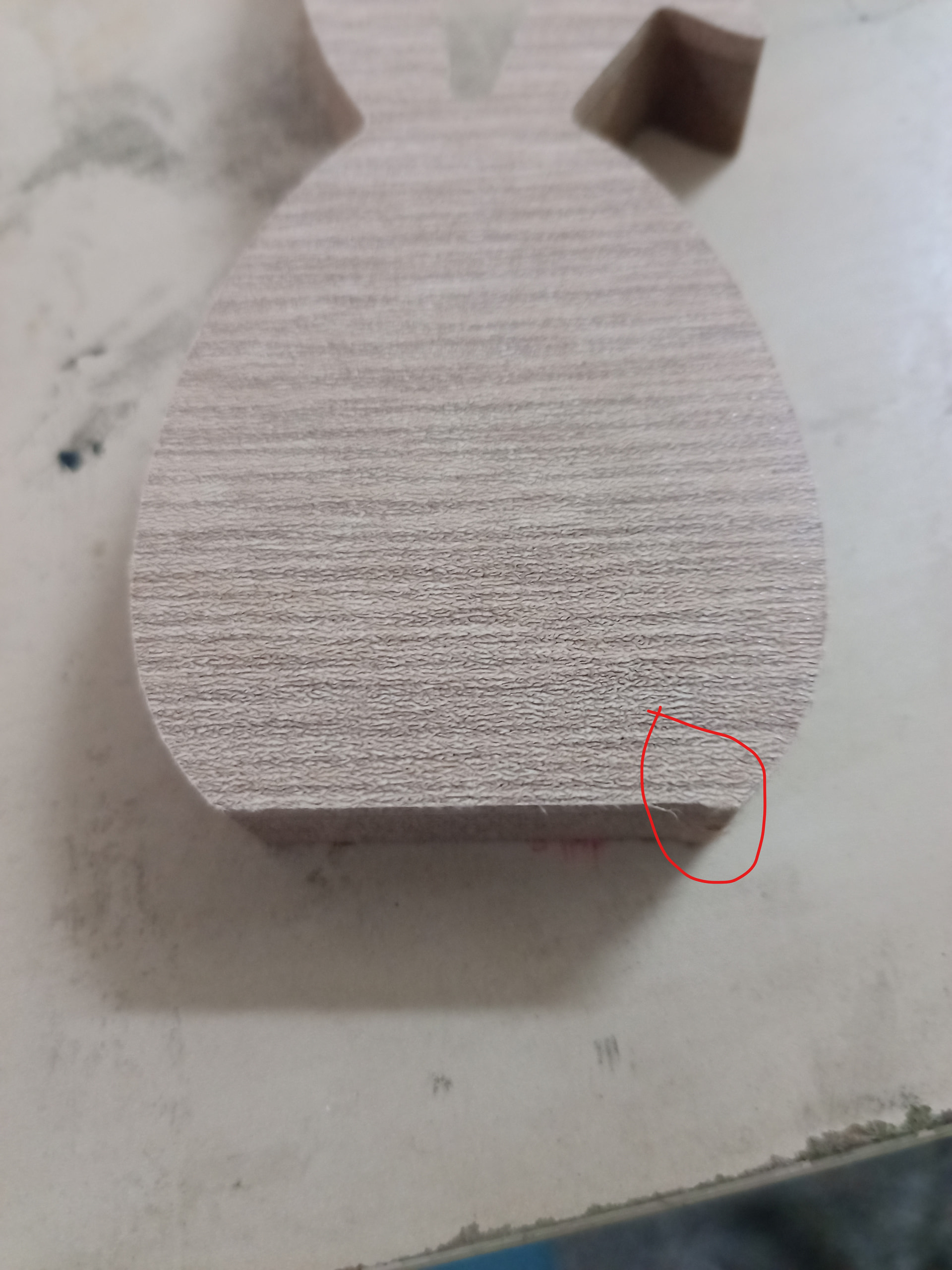
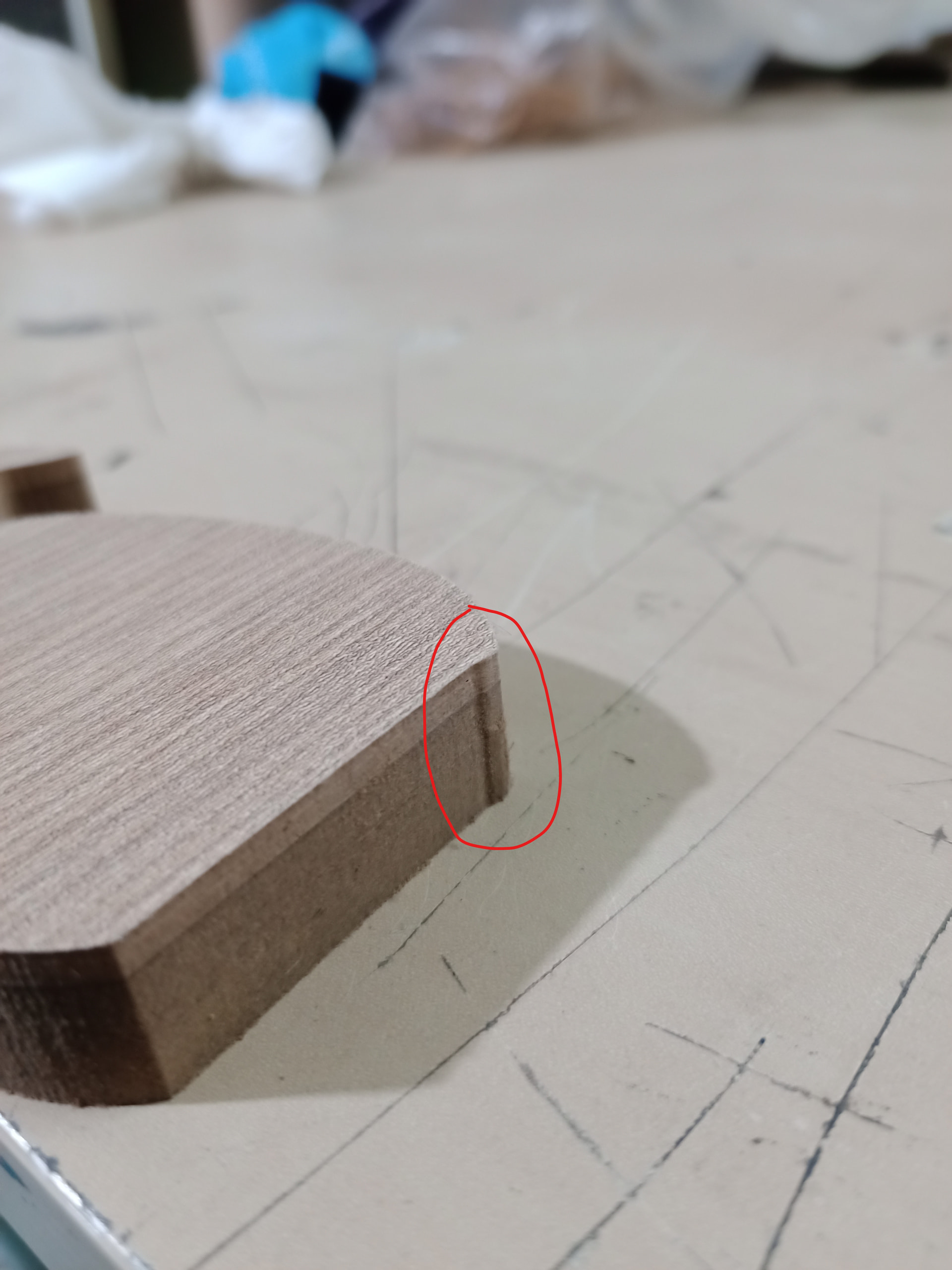
the problem is not the start point but in the program algorithm. I cut the same piece with mach3 (with code from Aspire with zig-zag and it came out as it should). When I cut I use Spiral. However, the program is still in beta and in this way it gives me three passes instead of two with Spiral.
Have you tried it with Vectric? Aspire is a 3D program for $2K, and it would be difficult to make a 1:1 comparison. MillMage is a 2.5D program, so we should use similar programs for comparison.
You did not comment on my last posting. It would be interesting to learn if adding a node would cure your “start here” problem.
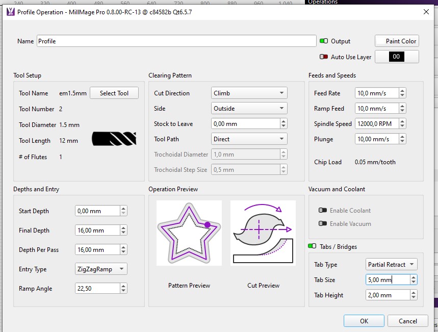
@fotis Your settings are very unusual; 1.5mm tool diameter, 12mm tool length, 16mm depth and 16mm Depth Per pass - are you using a different tool than specified in software?
Please attach the .mage and gcode file, or at the very least - even just the gcode file so we can backplot it and check the detail at that corner.
3 Likes
Here is the mage file. Yes, I placed a new node per vector and made that node a start node. For the interior cuts I made the cut start in the grain direction and the outer rectanglular shapes I made the start point at the bottom so it would be hidden bu another piece in the assmebly (not cut here).
I created these with Illustrator and exported from Illustrator as SVG then imported this into MillMage. I don’t know enough to say but this could explain why it may look odd. BTW, I’m no expert in Illustrator either ![]()
4x7 Table Top.mage (25.5 KB)
Thanks to those looking into this.
Oh and another reminder … I think I said this earlier … I am exporting all the operations and executing them using Gsender.
That should not make a diference.
I copied your left outer box to a new instance, added a similar tool, and played with it. A lot. I thought it was Tabs, but that was not it. I played with new Start Points, was not that either. But when I rotated the rectangle 90 degrees using the period key, the Start Point showed up in the correct location using Preview. However, when I went back into your file, rotating it had no effect.
I am guessing the algorithm that computes the cutter path overrides the moved Start Point due to the multiple shapes in the drawing. Why it does this is beyond my pay grade.