Problems with positioning when engraving and cutting

Hello everyone,

I wanted to engrave a larger Prokjet with lots of buttons and then cut them out.
60 round tags.
The emblem is the same on all the tags and there is also a number from 1 to 60.
I had 4 rows of 15 buttons each.

When I had finished engraving and cutting them out, it hit me.
Because the inner plates were all scrap, I could only use the outer ones. The engravings on the inner ones were offset, so they were double images.

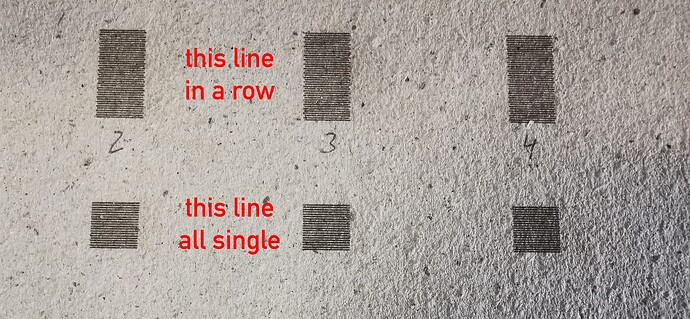
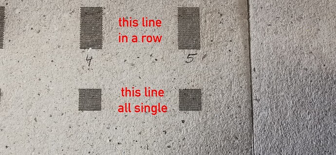
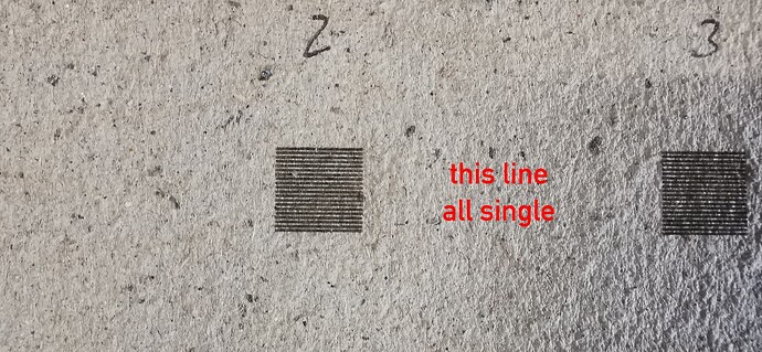
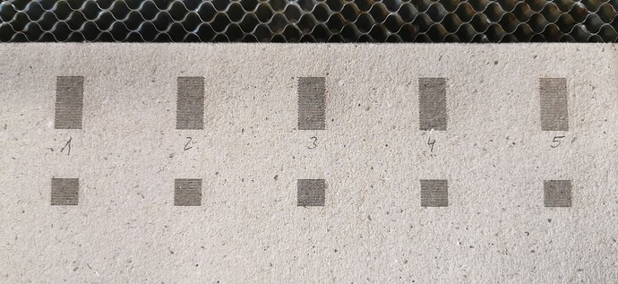
Then I started searching, filled squares with a line offset of 0.5mm so that you can easily recognize the start and end points of the line.
The first square fits, the second no longer does, the third is even worse and the last is okay again.

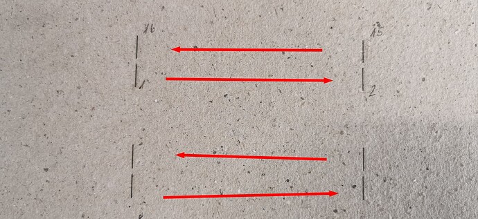
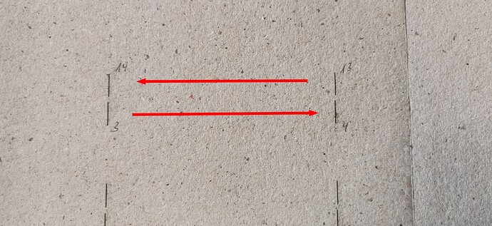
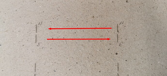
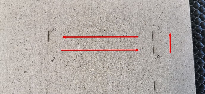
I then drew 10 mm long lines at a distance of 100 mm 8 pieces, my laser has an area of 900x600mm.
I then copied the lines and placed them underneath.
I then had these lines cut from left to right and the top row then from right to left.
Here, too, the first lines are in the same position, as are the last ones, but the others have an increasing deviation up to the middle and a decreasing deviation from the middle onwards.

I just can’t explain where this offset suddenly comes from.
Above all, why doesn’t it all fit at the beginning and end and in the middle?

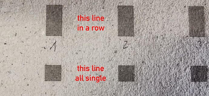
If I have the 10x10 boxes engraved individually, then they all fit, but if it engraves them in a line, then they don’t.

I have already made the acceleration so slow that it must have used 100mm right and left for braking and accelerating, but the result is always the same. I only engraved at 300mm/s. But even with 400 and 500 I have the same phenomenon.

Do any of you have an idea where I should look?
If the start and end are correct, regardless of whether I am engraving or cutting, then there can be no problem with the mechanics, or am I on the wrong track?

A few pictures to show what I mean.


My laser is an DLW9060 China import with Ruida RDC6445S(EC)
Leadshine 3Phases motor drivers 3DM580 and NN-Motors 3Phases stepper motor.
Look into this.

If I understand correctly, this is a new problem with an old machine. If that is the case, then it is almost certainly a mechanical problem. However, if it’s a new machine, then other problems are possible.

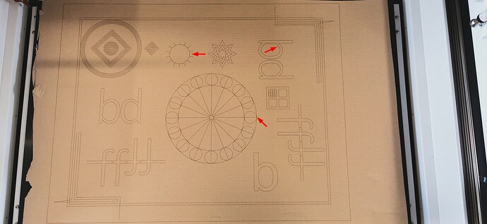
As a first step in debugging, scale this test pattern to fit the platform and run it as fast as it will go with the original high acceleration, in Line mode with optimizations turned off and power set to mark cardboard:

GrundTest.lbrn2

Any distortion in the results on the cardboard indicates a mechanical problem.

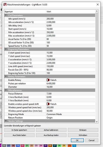
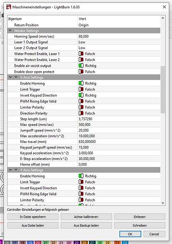
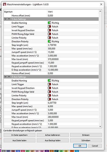
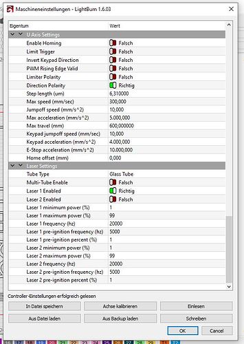
Upload screen shots of the Edit → Machine Settings → Vendor Settings for both the X and Y axes.

Hello Ed,

Thank you very much for your quick reply.

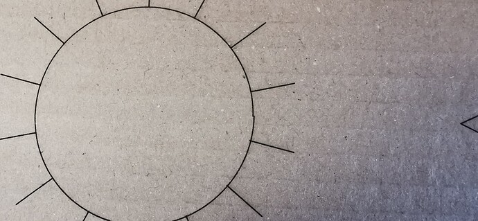
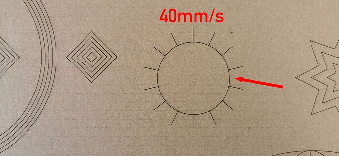
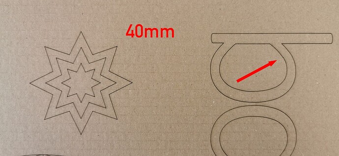
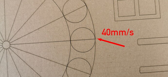
I did your test once at 25mm/s and once at 40mm/s.
Surely you could do it even faster with 60 or so…
I’ll be happy to submit this later.
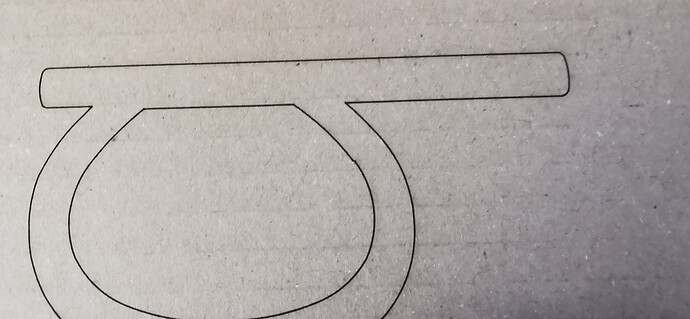
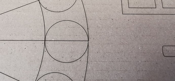
I noticed 3 errors in both molds, these errors are in both tests
exactly the same place in both tests.

I would say it is backlash, but why then only at these 3 points and at exactly the same position?
I worked with absolute coordinates.

I am looking forward to your expertise.
If you want to see all the pictures, how can I send them to you?


Best Udo


With a big CO₂ laser, you should be able to run it around 300 mm/s at high acceleration, using enough power to mark cardboard. The point is not to have a beautiful work of art, but to stress the machine as much as possible while producing a visible result.

I’ve given up trying to figure out why the world is the way it is, particularly with regard to laser machine hardware. :grin:

However, you now have a diagnostic test showing a mechanical problem. Your job is to find the backlash, fix it, then verify the fix using the same test.

Some previous discussion describe where other folks found obscure problems:

Good hunting!

1 Like

Hello Ed,

I had the graphic cut twice today at 500mm/s.
The first one also has the errors in exactly the same places at 500mm/s.
But here’s the thing, if I rotate your graphic by 180 degrees and look at the result, I still have the errors in the same places on the graphics, even though the positions on the table are now completely different.
I’m confused, do you have any ideas?

Best Udo

I do not know how to say this politely, so I ask your forgiveness in advance.

A poster hangs over my workbench with a list of Debugging Rules, the third one of which is:

Stop thinking and look

Without knowing the actual failure, we can spend the next month batting ideas back and forth, but that will not fix your machine.

You now have a test case triggering the problem, you have a list of places where the problem may lurk, so it’s time for you to get in there and learn something new. When you track down the loose or broken part, whatever it may be, the reason it causes the effects you’re seeing will become obvious.

So: stop thinking and look.

The reason I have that poster is because all too often I start trying to reason about a problem before collecting enough evidence to support any conclusions. It’s a hard lesson to learn! :slightly_smiling_face:

1 Like

Thats universaly good advice! even though I know nothing/not much about lasers…yet!.