Problems with settings for engraving a drawing onto a tile

My set up is scilpfun S30 pro 20W.

I have been using lasergrbl but have found that problematic with engraving tiles.
(the tiles are painted white, gold and black). I’ve inverted the image and I’ve been using 3000 @ 30% which sometimes works and sometimes doesn’t! The maximum time has been 1hr 50mins. In Lighburn’s preview this setting gives me a time of 3hrs 54mins.

I’ve messed around with speeds and %'s for example going to 8000 and 80% (10,000 per 10%). That gets the time down to 2hrs 2mins. I haven’t done a test print yet as I have two questions:

  1. I’ve heard that when changing figures it’s as simple as i’ve shown (10,000 per 10%). Is there a formula for increasing speed and strength that gives a more accurate ball park figure for a test print?

  2. My understanding is that for maximum detail the engraving speed should be 3,000 or less. Is this the case? If not is there a maximum speed before loss of detail is noticed and if so what is it?

What I am wanting to do is to reduce the engraving time without loosing too much detail and to hav a a range for carrying out tests.

I’ve attached a screen print showing my settings and the estimated time in lightburn,

You will soon discover paint thickness will have an impact on this.

Never heard this, but cannot confirm or deny. Does not make sense to me.

Detail is controlled by dot size and LPI. I suspect it is possible to have the laser move faster than the on-off firing can handle, but I doubt it.

(If) You are raster scanning a 4" square at 254 lines per inch. That means it has to sweep across the image over a 1000 times. That is going to take a while.

Do you know for sure your laser is capable of 254 LPI (0.1 interval)? What is the stated dot size? The larger number is usually the Yaxis. If you are scanning across the gantry, the line width will be the Yaxis value of the dot. Have you tried 200 LPI to see if there is a loss of detail? That will give you a 25% reduction in lines scanned.

Variations in materials and paint thickness is likely responsible for the hit-and-miss.

The time estimate is provided by a simulation and not directly from the controller. It’s a solid estimate. The simulation settings are under ‘Edit’ then ‘Device Settings’. When the estimates are off, it can be caused by an incorrect setting or an unexpected controller behavior. The settings can be fiddled with to produce adequate reults.

There is no precise formula. Generally, the behavior is ‘Linear… within a range…’. and the 10,000 per 10% might work between 60-90% or between 30-70%. It certainly might not work anywhere. It really can’t be known without testing.

It’s possible that 3000 mm/min and 30% is on the lower power limit of your engraver for marking your material. This can exaggerate the hit-and-miss behavior you’re reporting. The material test is the key to getting the speed and power settings that you need.

The material tests are key. The most noted contributor to tile engraving, Nicky Norton posted a picture a couple of weeks ago of a large pile of discarded test pieces in a plastic tub. If you want great results for one piece, you should expect to consume a minimum of 3-4 identical pieces in testing. Testing, marking up and discarding perfectly good material is the only way to get there.

These may be true but they’re absolutely machine-dependent and material-dependent. Material testing with your machine and your material are the only way to optimize. Recommendations from others may guide you where to begin your material tests but that is all that recommendations from others can ever be.

Going slow and turning the power down can shrink the dot size and enhance the detail. Most of the best tile engravings are done with a lower-power laser. These highly detailed tiles made with low powered lasers take a long time. The ability to pull detail may be limited by the larger dot created by a 20W laser.

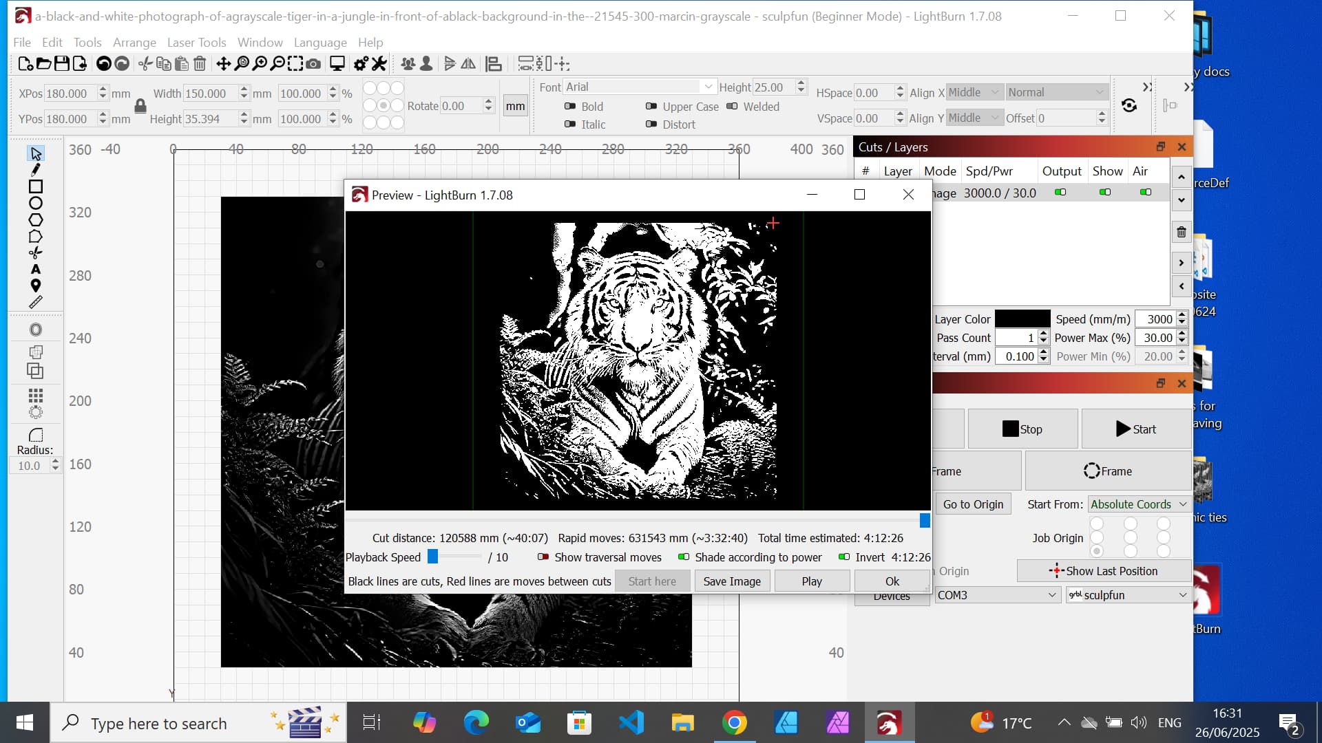
In the screenshot you’ve shared, the first thing I see is 'The Penalty of Speeding Up". The engraver spends time accelerating and decelerating after each line so it can change direction. It’s travelling almost three times further to slow down and stop and come back up to speed than it is travelling to engrave and produce the art. Acceleration is limited by machine rigidity. If the Force (mass x acceleration) causes the machine to deflect, it will mess up the engraving.

The preview is showing 3:32:40 (~3.5 hrs) of Rapid Moves. This is the time spent changing directions. If you turn on the ‘Show Traversal Moves’ switch in the Preview window you can see the Rapid moves (In Red), and any other non-engraving moves like the move from your ‘Start From’ to where the engraving begins.

The total estimated time is 4:12:40 (~3h 30m + 45m). The engraver is engraving for 45 minutes.

If you cut your engrave speed in half, the amount of time spent with Rapid moves should be halved (~1h 45m) or less.. The engrave time will double to 1h:30 but now you’re down to ~3h15 from ~4h15.

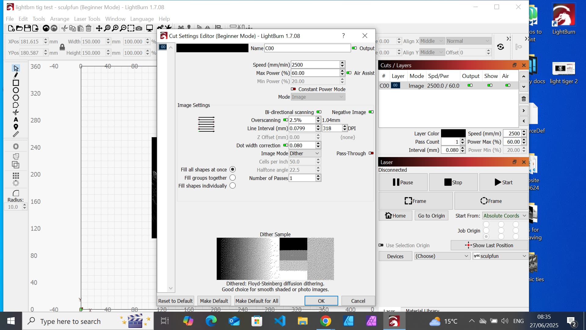
The next target is ‘dot size’. Most people believe that 600 dpi or more is great but the reality is, the engraved marks from the laser are more like drilling holes of a specified size. If you stack the holes too close together you just get one bigger hole. Folks will throw away all the contrast that would be available to them by not leaving enough space between the holes.

For the next step, pop open the Cuts / Layers settings and capture the screen to share it like you did previously. I’d like to know what was selected for Line interval or Dot size. Increasing the dot size or Line interval slashes time off both the Rapid move and Engrave move totals. It also enhances detail by not piling all the holes on top of each other. :slight_smile:

1 Like

Thanks for your reply.

My dot size was set at a default of 0.01. My machine is 0.08 so I changed it to that. That cut my time down to 1:20. I settled for that and did a test at 2500 and 60%.

There were two problems, the image is too dark and there is some banding :grimacing: With regards to the darkness: I will reduce the speed and if that doesn’t work I’ll play arround with the image settings.

The banding has been happening for a week now and I thought that I had sorted it out. It hasn’t happened for a whole day (after servcing the machine). The places where the banding occurse are random and it doesn’t happen with every engraving of this image (or of others). In a nutshell: I’ve serviced the machine and cleaned the lense. I also made sure that the laser module bar is straight, rolls freely when the machine is at a 45 degree angle and that the laser modue axis is level.

I am begining to think, with good reason, that the problem is caused by me pausing the engraving and restarting it, I did this to check if the setting was OK for the job.

I also thought that the banding was a lasergrbl issue but it has hapened with my first job on lightburn. The banding is why I switched back from Lasergrbl.

I’ll raise another topic if the banding occurs again and submit a few pictures to show the banding.

1 Like

Thanks.
The dot size was an issue. The default size was 0.01 but my machines size is 0.08. I’m used to working at L/mm in lasergrbl (1/0.08 -12).

With regards to engraving ceramic tiles. I have tried the NWT method but I couldn’t get it to work. Short version, out of frustration I tried a setting of 1000 and 80% the end resukt was still a very light grey. I’m going to come back to this during the autumn.

Last week, I decided to try the paint method and it worked without too much trouble. I managed to make 4 tiles and sold them all so I decided to continue with it for this week. So far I’ve managed to make 1 and throw away 7 tiles becuase of various problems. Arghh!!!

2 Likes

Interesting about my settings being at the lower end of the machine’s capability. I’m beginning to think that engraving is too technical for me. I’ll see how I get on with solving this issue (with help).

I do do test prints. As a rule I try a miniture full version between 40 and 50cm (for a general setting) and then select an area of at least a third from the full size image. Usually, where there is the most tonal range (to fine tune it). However, I’m beginning to think that I don’t need the smaller image.

Both test print results were very good but the final result was too dark.

I’ve attached a screen print of the new settings. It’s down to 1:45. The result was very dark but I can adjust speed and picture settings to solve this.

1 Like

Hi Tony

Which mode are you using to create the image.

I am using image. It seems to be a default setting as I can’t change it or don’t know how to change it. If it can be changed can you let me know how? Thanks.

With regards to banding. It never used to happen, it started when I started to engrave tiles (larg size). I used to engrave coasters of various materials. I did think that maybe it happened with the coasters but isn’t visible. I’ve looked at several through a magnifyer and found no evidence of banding.

I’ve been reading upon the causes of banding. The only options left for me to try are:

I had the engraver and PC running from the same socket (extension lead). I’ve now plugged them in seperate sockets.

Changing the printer cable.

I’ve attached a screen print that shows my settings.

With regards to the banding. I’ll try a few things out today. If that doesn’t work I’ll raise it as a new topic.

I’ve just spotted that the line interval setting. I have no idea if that is correct or not. I’ll read up on it. 0.0799 and 314DPI

Tony

Go to Lightburn Documents and search image mode.

You can see it in the pic you posted above, You are using/set to ‘dither’ in this case. If you click the down arrow you will see a list of other options for Image quality.

“Image Mode is a special engraving mode for images, which works similarly to Fill Mode, but allows you to select an additional image processing mode that affects the appearance of the engraving.”

Well worth exploring!

Also in LB Doc’s

“5 Steps to Perfect Image Engravings”.

This should really clue you in…look for “Dot correction”. There is also a brilliant video by ‘If I recall correctly’ Russ Saddler, Its posted somewhere here on LB forum but you should find it on YT. He explains it all very well.

Very interested in your progress and hope you figure out the banding (post a pic if you can).

Russ Sadler, as far as I know, focused on RDWorks, not Lightburn. I’m guessing that you mean the Laser Everything video on photo engraving.

I agree, he should watch this video… if I remember the dot correction is ~1/2 of the dot width.

When they were talking about line mode, I thought I saw image in your layer.

With an image, there is not other option. You can trace it to create a vector file. Either will generate lots of gcode.

:smiley_cat:

1 Like

Thats the one, thanks Jack. Also Russ Saddlers video on dot size and graphics is a masterclass..in my opinion and really clued me in.

I have his rack and pinion drive, lightweight head and the m1/tube holder in my machine. I like the way he presents things.

:smiley_cat:

1 Like