Problems with XPro V5 Spark Concept in Laser Mode

Hi!

For many months I try to add a Laser Module to my CNC mill. I have Nema 23 and therefore I was looking for a compact solution having the stepperdrivers built in.
I made a completely seperate controller conecpt.
The controller is a new XPro V5 from Spark Concepts, using GRBL, connected via USB to my Windows 10 Notebook.
When I flash firmware, I do this - as recommended via access point connection directly to the XPro. No matter which device I use or which firmware I flash, the console in Lightburn will tell me $i will not change the name of the firmware to the correct and recently uploaded filename. But obviously something “arrives”, as the controller reboots after flashing and firmware for normally closed end stop can be changed to normally opened. The console recognizes the change and also the NC in the file name changes:
from [MSG:Using machine:CNC_xPRO_V5_XYYZ_BM3D_NC]
to [MSG:Using machine:CNC_xPRO_V5_XYYZ_BM3D_NO]

The rest of the filename will not be accepted. The console will alway tell
CNC_xPRO_V5_XYYZ_BM3D_NC or NO even after flashing firmware named CNC_xPRO_V5_XYYZ_LASER_NC

Any ideas? Spark Concept did not help me. I was only sent in circles with tenths of emails, doing this test, doing that, but no answer how this is possible or how it can be solved - 6 weeks now!!!

Furthermore, it is really dangerous using this controller. The PWM is ALWAYS (while controller is powered or even just connected via USB, power supply switched off!, no matter which firmware I flash) at least at 1,35V. By the way, the switch at the controller is set to PWM. I can only start the system when sending the PWM through the relay of the XPro. Otherwise it will fire directly at high power in the moment I start the controller. I got almost blind. But even after using the relay, the laser will fire for a second in the moment I start LightBurn. To me that’s a safety issue.

My question is: Am I completely wrong? Is it okay that firmware flashing behaves like this? Is it normal that PWM is always at 1.35V or higher?

I am not a specialist and hope someone can help me. Spark Concepts is not helpful. Just after me begging for help they now offered me to send it in. I am not sure I will get it back - as it seems they are not interested in solving this issue. Emails are not answered for days, and when they are I am asked to do another test. Sending it in from Germany will take weeks until I get it back. Makes no sense to me anymore as long as the correct firmware doesn’t arrive on the controller. Or do I miss something?

Any help is appreciated.

Thanks in advance

Matthias

I did some research on your unit and it’s a bit confusing.

A few questions and clarifications please.

  1. What laser module do you have? I suspect the firmware with laser in its name is meant specifically for BM3D laser module but it’s not clear what’s different about that laser and consequently the firmware.
    In any case, it seems that the firmware you probably want to go with is “CNC_xPRO_V5_XYYZ_NO.bin” as that seems configurable and is considered the standard firmware.
  2. Have you set these parameters?
$Spindle/Type=Laser
$Gcode/LaserMode=on

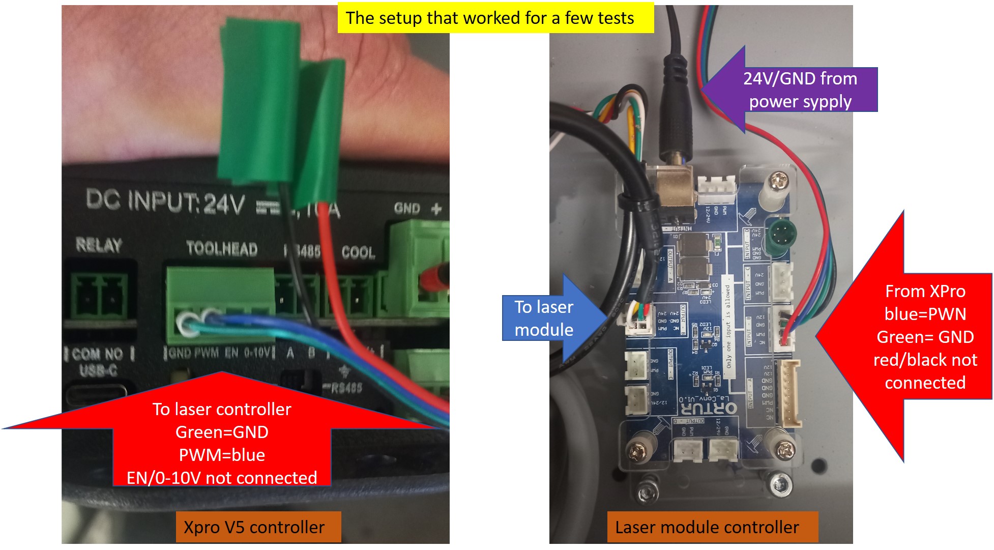
How have you wired the laser to the controller? You need to be on GND and PWM pins of Toolhead.
In normal GRBL configurations you’d get 0V when power is set to 0% and 5V at 100%.

It could just be an issue in how the message has been setup during compilation of the firmware. Or perhaps they’ve mislabeled the firmware. In any case, I suggest you update the firmware I listed unless you specifically have a BM3D laser module.

I’m not familiar with your specific controller but it’s almost certain you do not want a relay between PWM and the laser module. It will basically make it impossible to control your laser properly.

  1. Can you run these commands in LightBurn Console and return output?
$I
$$

Hi berainlb!
Thanks for your nice and quick response. I will try to answer all questions as good as possible.

Thanks again for you help!

Matthias

Enable input is unnecessary as power is determined entirely by PWM.

Did they give any indication as to how BM3D would behave differently?

If this were any other controller I would say this mostly likely seems like a hardware failure. However, from the little I’ve read on this there are many peculiarities I’m not certain I’m fully understanding so it’s possible there’s still a configuration issue or something else causing the issue.

This makes me think this could indeed be a hardware failure.

This is a bit odd. Normally this would be 0. Can you run this in Console and see if voltage at 0% power changes?

$31=0

The wiring for the laser seems fine. Can you try a couple of things?

  1. Can you toggle the PWM<>RS485 switch a couple of times to make sure it’s getting properly indexed to PWM?
  2. Can you try running something at 100% power and check the voltage from PWM? You don’t need the laser actually connected for this. Just interested in PWM voltage.
  3. Can you run these commands in Console and return results? I’m not familiar with these settings so want to make sure I’m seeing everything that’s available.
ExtendedSettings/List
Settings/List
GrblNames/List

Did some additional research.

Most relevant issue seems similar to this one:
PWM 5V on Constant - TTL Laser Control · Issue #23 · Spark-Concepts/xPro-V5 · GitHub

So run a couple of tests in addition to what I’ve already posted:

  1. Can you check PWM voltage at a few different levels? 0%, 1%, 50%, 100%?

There’s an interesting comment about the internal pull-down resistor for PWM to be fairly weak which is potentially allowing the PWM voltage to float fairly high. Do you have a resistor you could place between PWM and Ground? They recommend one in the range of 1K - 4.7K Ohms.

Hi!

Cool, thanks.

  • I did switch between RS485 several times in the past. The difference is, that on RS485 the voltage between pwm and gnd is 3.5V.

One question before I add the resistor, hoping to prevent anything from going up in smoke:
Do I connect it between the pwm host and the pwm wire or between pwm and gnd, directly at the plug? I have a 1K resistor here.

Thanks!

Matthias

And here are the settings:
$ExtendedSettings/List

$0=8

$1=255

$2=0

$3=7

$4=0

$5=1

$6=1

$10=1

$11=0.010

$12=0.002

$13=0

$20=0

$21=1

$22=1

$23=3

$24=200.000

$25=500.000

$26=250.000

$27=10.000

$30=1000.000

$31=0.000

$32=1

$N1=

$N0=

$33=5000.000

$34=0.000

$35=0.000

$36=100.000

$100=320.000

$101=160.000

$102=320.000

$103=200.000

$104=100.000

$105=100.000

$110=2500.000

$111=2500.000

$112=2500.000

$113=1000.000

$114=1000.000

$115=1000.000

$120=50.000

$121=50.000

$122=50.000

$123=200.000

$124=200.000

$125=200.000

$130=590.000

$131=1100.000

$132=300.000

$133=300.000

$134=300.000

$135=300.000

$140=1.800

$141=1.800

$142=1.800

$143=1.800

$144=0.800

$145=0.800

$150=0.250

$151=0.250

$152=0.250

$153=0.250

$154=0.400

$155=0.400

$160=8

$161=8

$162=8

$163=16

$164=16

$165=16

$170=16

$171=16

$172=16

$173=16

$174=16

$175=16

$Settings/List

$Sta/SSID=CNC_xPRO_V5

$Sta/Password=******

$Sta/IPMode=DHCP

$Sta/IP=0.0.0.0

$Sta/Gateway=0.0.0.0

$Sta/Netmask=0.0.0.0

$AP/SSID=CNC_xPRO_V5

$AP/Password=******

$AP/IP=192.168.0.1

$AP/Channel=1

$System/Hostname=CNC_xPRO_V5

$Http/Enable=ON

$Http/Port=80

$Telnet/Enable=ON

$Telnet/Port=23

$Radio/Mode=AP

$Bluetooth/Name=xPRO_V5_BT

$Notification/Type=NONE

$Notification/T1=

$Notification/T2=

$Notification/TS=

$Message/Level=Info

$User/Macro0=

$User/Macro1=

$User/Macro2=

$User/Macro3=

$Homing/Cycle0=Z

$Homing/Cycle1=XY

$Homing/Cycle2=

$Homing/Cycle3=

$Homing/Cycle4=

$Homing/Cycle5=

$Report/StallGuard=

$Stepper/Enable/Delay=0

$Stepper/Direction/Delay=0

$Stepper/Pulse=8

$Stepper/IdleTime=255

$Stepper/StepInvert=

$Stepper/DirInvert=XYZ

$Stepper/EnableInvert=Off

$Limits/Invert=On

$Probe/Invert=On

$Report/Status=1

$GCode/JunctionDeviation=0.010

$GCode/ArcTolerance=0.002

$Report/Inches=Off

$Firmware/Build=

$Limits/Soft=Off

$Limits/Hard=On

$Homing/Enable=On

$Homing/DirInvert=XY

$Homing/Squared=

$Homing/Feed=200.000

$Homing/Seek=500.000

$Homing/Debounce=250.000

$Homing/Pulloff=10.000

$GCode/MaxS=1000.000

$GCode/MinS=0.000

$Laser/FullPower=1000

$GCode/LaserMode=On

$GCode/Line1=

$GCode/Line0=

$Spindle/Enable/Invert=Off

$Spindle/Enable/OffWithSpeed=Off

$Coolant/Delay/TurnOn=1.000

$Spindle/Delay/SpinDown=0.000

$Spindle/Delay/SpinUp=0.000

$Spindle/PWM/Invert=Off

$Spindle/PWM/Frequency=5000.000

$Spindle/PWM/Off=0.000

$Spindle/PWM/Min=0.000

$Spindle/PWM/Max=100.000

$Spindle/Type=LASER

$X/StepsPerMm=320.000

$Y/StepsPerMm=160.000

$Z/StepsPerMm=320.000

$A/StepsPerMm=200.000

$B/StepsPerMm=100.000

$C/StepsPerMm=100.000

$X/MaxRate=2500.000

$Y/MaxRate=2500.000

$Z/MaxRate=2500.000

$A/MaxRate=1000.000

$B/MaxRate=1000.000

$C/MaxRate=1000.000

$X/Acceleration=50.000

$Y/Acceleration=50.000

$Z/Acceleration=50.000

$A/Acceleration=200.000

$B/Acceleration=200.000

$C/Acceleration=200.000

$X/Home/Mpos=0.000

$Y/Home/Mpos=0.000

$Z/Home/Mpos=0.000

$A/Home/Mpos=0.000

$B/Home/Mpos=0.000

$C/Home/Mpos=0.000

$X/MaxTravel=590.000

$Y/MaxTravel=1100.000

$Z/MaxTravel=300.000

$A/MaxTravel=300.000

$B/MaxTravel=300.000

$C/MaxTravel=300.000

$X/Current/Run=1.800

$Y/Current/Run=1.800

$Z/Current/Run=1.800

$A/Current/Run=1.800

$B/Current/Run=0.800

$C/Current/Run=0.800

$X/Current/Hold=0.250

$Y/Current/Hold=0.250

$Z/Current/Hold=0.250

$A/Current/Hold=0.250

$B/Current/Hold=0.400

$C/Current/Hold=0.400

$X/Microsteps=8

$Y/Microsteps=8

$Z/Microsteps=8

$A/Microsteps=16

$B/Microsteps=16

$C/Microsteps=16

$X/StallGuard=16

$Y/StallGuard=16

$Z/StallGuard=16

$A/StallGuard=16

$B/StallGuard=16

$C/StallGuard=16

$GrblNames/List

$ESP100 => $Sta/SSID

$ESP101 => $Sta/Password

$ESP102 => $Sta/IPMode

$ESP105 => $AP/SSID

$ESP106 => $AP/Password

$ESP107 => $AP/IP

$ESP108 => $AP/Channel

$ESP112 => $System/Hostname

$ESP120 => $Http/Enable

$ESP121 => $Http/Port

$ESP130 => $Telnet/Enable

$ESP131 => $Telnet/Port

$ESP110 => $Radio/Mode

$ESP140 => $Bluetooth/Name

$0 => $Stepper/Pulse

$1 => $Stepper/IdleTime

$2 => $Stepper/StepInvert

$3 => $Stepper/DirInvert

$4 => $Stepper/EnableInvert

$5 => $Limits/Invert

$6 => $Probe/Invert

$10 => $Report/Status

$11 => $GCode/JunctionDeviation

$12 => $GCode/ArcTolerance

$13 => $Report/Inches

$20 => $Limits/Soft

$21 => $Limits/Hard

$22 => $Homing/Enable

$23 => $Homing/DirInvert

$24 => $Homing/Feed

$25 => $Homing/Seek

$26 => $Homing/Debounce

$27 => $Homing/Pulloff

$30 => $GCode/MaxS

$31 => $GCode/MinS

$32 => $GCode/LaserMode

$N1 => $GCode/Line1

$N0 => $GCode/Line0

$33 => $Spindle/PWM/Frequency

$34 => $Spindle/PWM/Off

$35 => $Spindle/PWM/Min

$36 => $Spindle/PWM/Max

$100 => $X/StepsPerMm

$101 => $Y/StepsPerMm

$102 => $Z/StepsPerMm

$103 => $A/StepsPerMm

$104 => $B/StepsPerMm

$105 => $C/StepsPerMm

$110 => $X/MaxRate

$111 => $Y/MaxRate

$112 => $Z/MaxRate

$113 => $A/MaxRate

$114 => $B/MaxRate

$115 => $C/MaxRate

$120 => $X/Acceleration

$121 => $Y/Acceleration

$122 => $Z/Acceleration

$123 => $A/Acceleration

$124 => $B/Acceleration

$125 => $C/Acceleration

$130 => $X/MaxTravel

$131 => $Y/MaxTravel

$132 => $Z/MaxTravel

$133 => $A/MaxTravel

$134 => $B/MaxTravel

$135 => $C/MaxTravel

$140 => $X/Current/Run

$141 => $Y/Current/Run

$142 => $Z/Current/Run

$143 => $A/Current/Run

$144 => $B/Current/Run

$145 => $C/Current/Run

$150 => $X/Current/Hold

$151 => $Y/Current/Hold

$152 => $Z/Current/Hold

$153 => $A/Current/Hold

$154 => $B/Current/Hold

$155 => $C/Current/Hold

$160 => $X/Microsteps

$161 => $Y/Microsteps

$162 => $Z/Microsteps

$163 => $A/Microsteps

$164 => $B/Microsteps

$165 => $C/Microsteps

$170 => $X/StallGuard

$171 => $Y/StallGuard

$172 => $Z/StallGuard

$173 => $A/StallGuard

$174 => $B/StallGuard

$175 => $C/StallGuard

The latter, directly at the plug. Although I see now that the user tried that with a 3K Ohm resistor and still had a very low 0.1V value. So a 1K Ohm resistor may not get you all the way there but still worth a shot.

This is not promising. The symptom in the other thread was high idle voltage but that when commanded voltages went to normal levels.

In any case, it looks like this uses 3.3V logic so 100% is 3.3V, not 5V. That means your minimum power is around 41%.

Controller problem, right?

Cheers and thanks again

Matthias