Project is out of bounds very where.
Sorry for this long discussion, but there is a lot of information about the out of bounds problem.
I have a DIY diode laser system that is built around lead screws. It has been working for a long time.
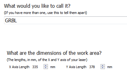
It runs in the 3rd quadrant. (home in the front/left corner). The work space is a little strange just because. Xmax = 335, Ymax=378 mm.
Running GRBL 1.1f software. On a Woodpecker CNC CAMX TOOL v3.4 controller board.
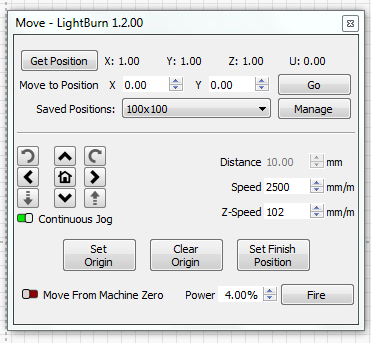
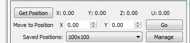
All of the manual controls move the laser any where up to Xmax,Ymax. “Go to origin, Home, Saved Position, Move to, Jog, R/L F/B.” Preview is okay. Soft limits work.
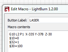
Because 0,0 starts out at back/right, I use a macro shown below for offset to front/left.
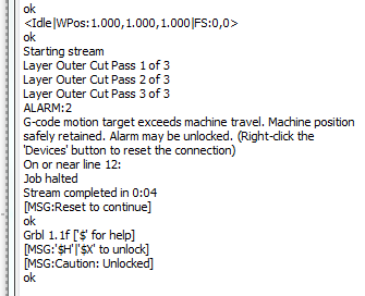
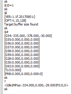
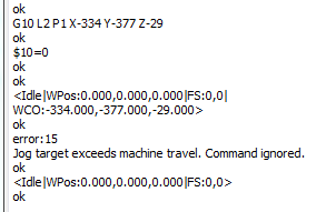
THE PROBLEM. This just started out of the blue. Was using LR v1.1.0 when problem started. Updated to v1.2.00. No changes. Using a small rectangle for the project, no matter where the laser and rectangle are, START causes the “out of bounds” error message shown below. Laser is shut off. Fire doesn’t work.
Over many hours the past 2 weeks, I have tried many many changes and combinations of settings with no improvement. Replaced the Woodpecker controller board. Reversed XY motor directions in $3. That just reversed the L/R B/F controls. Homed okay. Removed G10 from marco. That upset the position polarity. Yes, I’ve restarted the computer and power supplies many times. Off over night.
I had a couple of projects to do. One is gone.
I’m at a loss of what to do! Any ideas?
Your setup is a little unusual so I want to make sure I understand it.
Can you confirm:
You home to the bottom-left.
However, your origin is set to top-right? And work in Quadrant 3?
Questions:
Do your jog controls work in the expected direction?
Is homing currently working correctly?
Your $30=100 value is unusually low. Is this deliberate?
Is there a particular reason you want the origin to be top-right?
Is there a reason why you are using macro for your GRBL changes? Do those settings not persist across power cycles of the controller? As in, will these settings not be in effect if you don’t set them each time?
Can you provide the following:
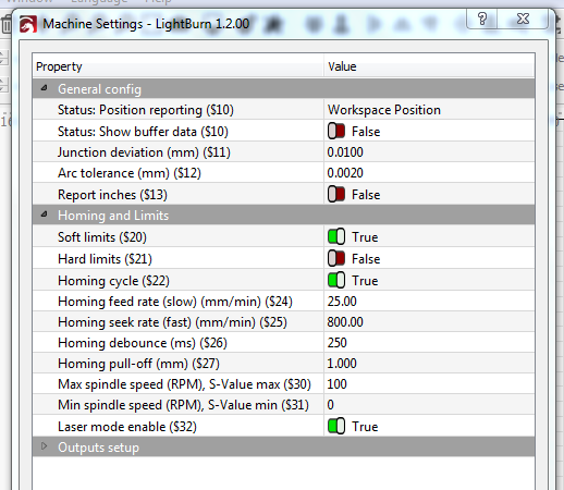
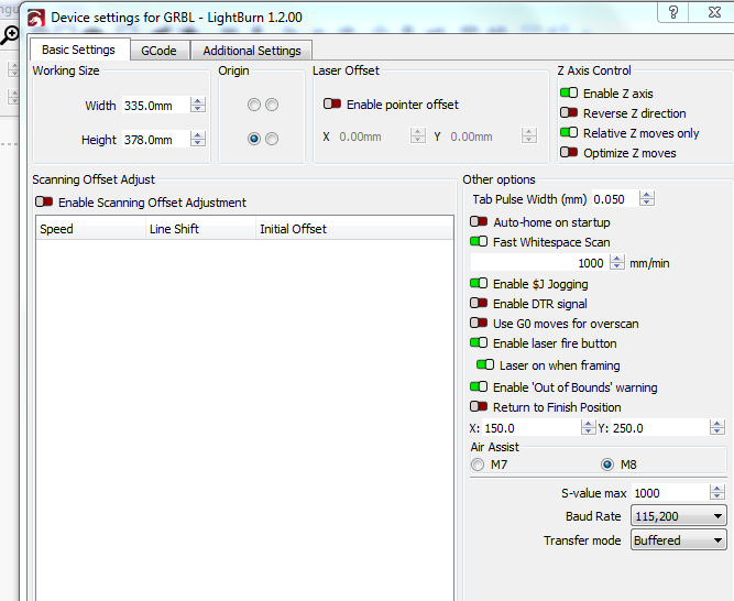
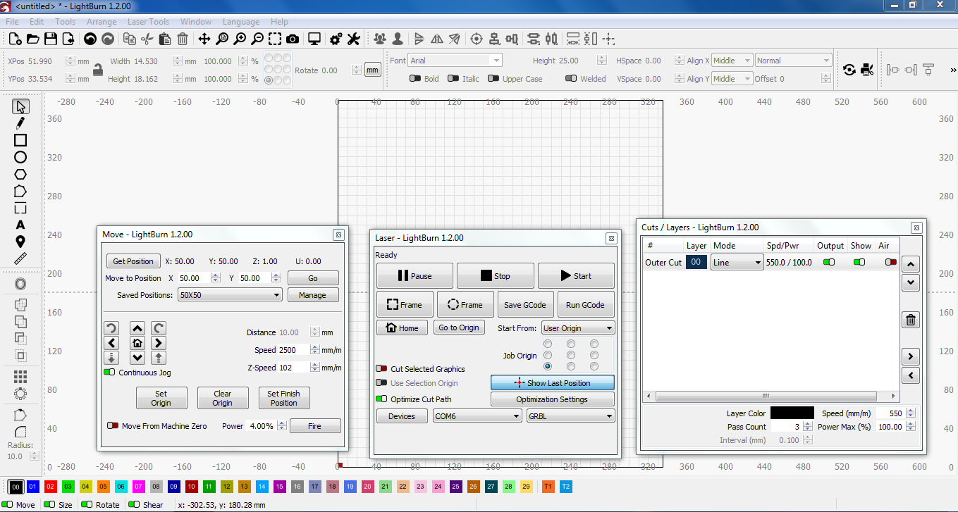
Screenshot of Edit->Device Settings
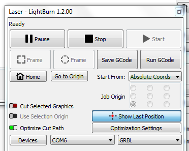
Full screenshot of LightBurn
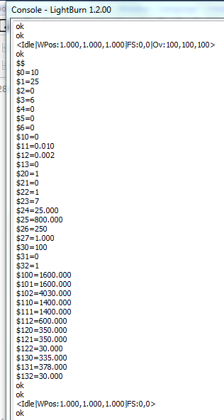
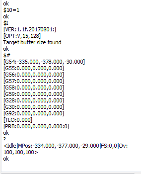
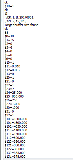
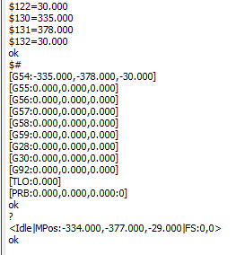
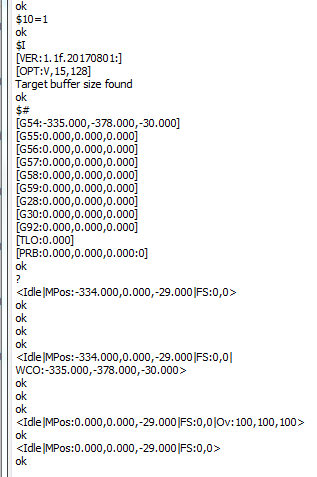
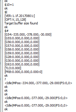
Complete a homing cycle and then run the following. Return the text back please:
Thank you berainlb for your quick reply. This is my 1st post and slow learning how to use it. Will try to get thu your questions.
Confirm:
Home is to bottom-left.
Do work in Q3. Lower/left My original laser engraver was an Ortur belt driven system. And just change ever thing to lead screws. 0,0 back then was back/right.
Questions:
Jog controls work.
2.Homing works.
3 $30 = 100 is my mistake. May have thought it was 100%.
No It should be front/left.
Macro was the original solution to the back/right 0,0 problem. Not sure it sticks on power down. I thought it made a difference. Now realize it may just be the $32=1switch.
Tests:
1.2. See screen shots.
Hope I ran the tests as requested. Before each corner test, ran the setups.
Each test is just numbered “#n”. I didn’t repeat the $$ each time. Couldn’t get it all on the screen at once.
Really appreciate your time and effort looking at this. It must not be a simple problem. Just hope it has a solution. Phil
Okay. Based on what I’m seeing most of your setup should be correct. I’m not following that your machine is working in Quadrant 3 but let’s make a few changes and run some tests.
Let’s fix this. Run in Console:
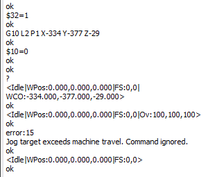
$30=1000
I’m going to guess you don’t need to do apply this each time. Af for $32, do you use this machine also for CNC operation? If so, you may need to toggle back and forth between laser and CNC operation.
Let’s tweak your offset by 1 mm. Please run in Console:
G10 L2 P1 X-334 Y-377 Z-29
$10=0
Then home the machine and then run in Console:
?
This should be 0,0.
Then move machine to top-right and then rerun ? command and return results.
Hi berainlb
I’ll start by explaining how I came up with Quadrant 3.
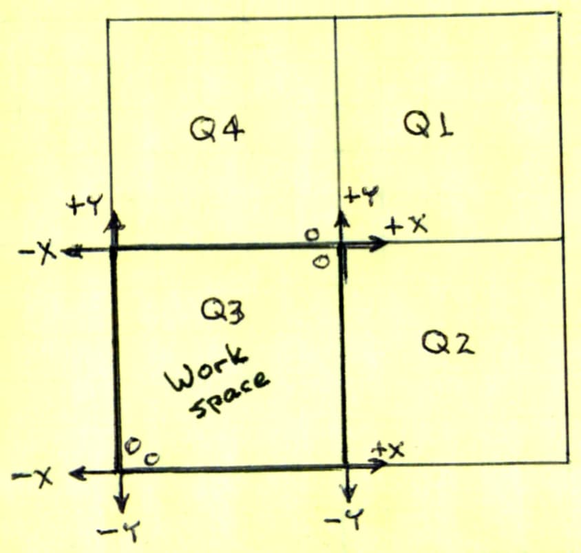
My first laser engraver was an Ortur belt driven gantry. Changed to my laser and a WoodPecker controller board. When I tried to run a project, the laser went up to the right/back corner and jammed. That implied to me that +X,+Y must be beyond that corner (Q1 - more to the back/right). Then I found an article from the Lightroom people that said that in that case I would have to set up a macro with G10 … X-x Y-y. That shifts the positive numbers from LightRoom down into the work space. You know that.
See drawing: The x,y are from LR if negative numbers could be sent. Q1 without G10. Q2 to the right of work space. Q4 back of workspace. And Q3 works with G10 shifted x,y.
Changed $30=1000 Now matches the S-value max in Devices Settings.
This machine is only used as a laser engraver/cutter not CNC.
Ran G10 L2 P1 X-334 Y-377 Z-29
$10=0
Home then ? Ran twice to make sure I didn’t make a mistake.
Tried to use JOG to move to corners. The 1st JOG caused the error 15. No more moves.
$10=0 What does that set the Status Report to? 1 would be Machine Position and 2 is Work Position. Could that make a difference in what numbers are being used somewhere?
One more question. $3 sets the motor directions. And $23 sets the Homing Cycle Direction. Seems like that should be the same. Same motors - wired the same. I spent a lot of time coming up with $3=6 and $23=7.
I hope you are not spending too much time on this. But I do appreciate what you have done. Maybe something will pop up that is not right. Phil
Ah… I’m following you and agree. I was just thinking that with the offset you’re no longer working in a Quadrant 3 manner. With the offset you’re effectively working in Q1. I don’t know if there’s a convention that determines the true quadrant.
That’s interesting and completely unexpected.
$10=0 actually sets status to report working position. 2 actually enables buffer data.
The intent of Work Postion in this is case is so that it’s reporting coordinates with the work offset (WCO) accounted for.
So value after homing is good (0,0).
I think the issue may be with Z axis. Can you disable Z axis in Edit->Device Settings and see if it works? If so, you may need to remove the Z portion of the offset:
G10 L2 P1 X-334 Y-377 Z0
I don’t think these necessarily have to be the same. GRBL by default I believe homes toward the positive value direction for each axis. I think this is a legacy from CNC where you’re typically working in negative coords. As long as your jogging controls work in the correct direction and homing works in the correct direction you should okay.
Happy to help with this… especially when you’re already so close to it.