This will be an ongoing thread (hopefully not too long) - using my real world experiences, to help me and help others.
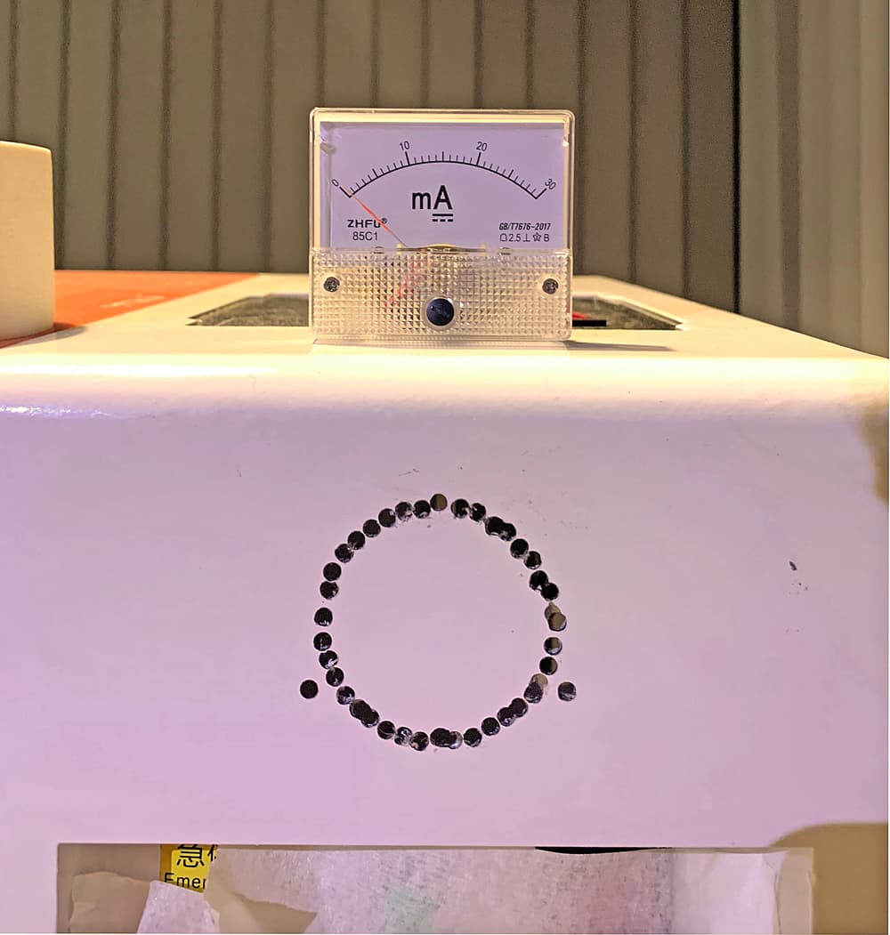
So, finally, I’ve purchased a mA meter. It’s 30mA, which from what I’ve read is suitable. It doesn’t show on the terminals which connection is positive or negative.
I used my multi-meter tester in continuity mode and saw the needle go upwards, depending on the polarity which way I switched the wires around. So I assume that the positive (red) wire on my multi-meter corresponds to the positive connector on the mA meter.
I’m not sure if this is correct or if damage can be done when connected into the Laser circuit and the polarity is backwards.
A bit more work to do on cutting out the hole (tomorrow).
When that part is done, then I cut the black wire coming from the negative side of the laser tube. The Cathode?. In any case, I should cut the wire from negative side of the tube and insert the mA meter in that path?
The wire that is directly from the tube goes to the positive terminal of the mA meter, the other side terminal continues it’s path to where it came from.
Is this correct? I there something I’ve forgotten?
I spliced into mine close to the lps. Where ever it’s the most convenient will work. The cathode end is the negative (or ‘cold’ end), that’s correct. Give yourself some extra wire on each side. I soldered them and used heat shrink tubing to seal them… probably overkill…
The wiring is correct, as the positive side goes towards where the positive charge is and other goes to negative or ground.
There’s no danger…
Check it before you load it… When you get it installed, pulse it at low power, short duration and you can tell if you need to swap the polarity. It will just ‘nudge’ the needle. Probably much less than your ohm meter…
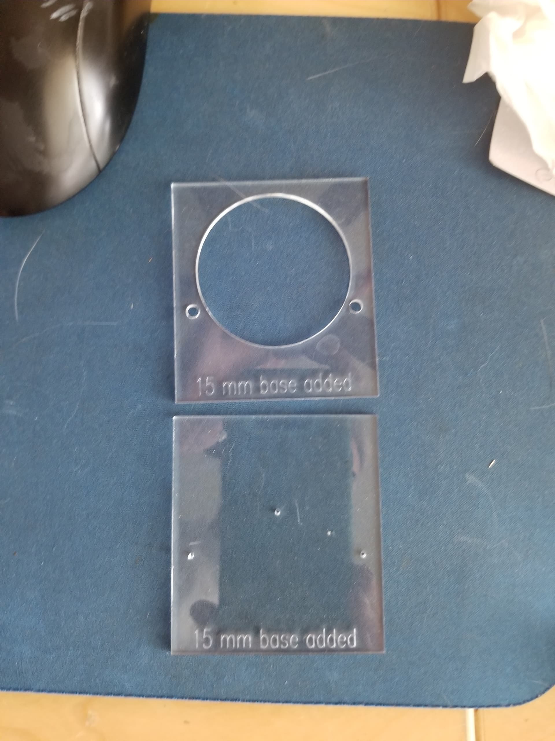
I use a template of the meter to locate where I want it. The other template has drill guides for the mounting bolts and a center point. The center point is for a hole saw…
I will be doing a series of power reading tests, so what am I expecting in the way of mA readings for a 40 watt laser tube?
The tube is 700mm long and 50mm diam. so I’m assuming that 40 watts is correct. There is no specs on the tube, in fact I have no idea what brand it is so I can’t search for it.
My power supply is 50 watts.
So I guess the question is what maximum milliamps should I safely run the tube at?
I did do some reading a while back (Russ Saddler) but he was using a 60 watt tube (I think) and if I remember 21 mA was the max?
Lots of people here with your type of laser or at least tube size… and it would be best from one of them. I do remember people advising 14mA as an average. I’d wait for someone with one to advise you about a possible max.
Here’s one I looked at and he suggests up to 18mA, but I think it’s high. I’ve seen larger tubes (like Russ) that were 60 watt tube limited to 21mA. I just set it to the test maximum.
I have an 880mm tube, that it’s tests sheet showed the max current at 21mA. I set the supply to 10.5mA at 50% power. I’ve been running this way since I received the machine, over a year anyway.
It’s a 50 watt China Blue, that reads 44 watts on a Mahoney.
Good luck, nice looking install.
IMHO, the only way to ensure you stay under your current limit is with an lps adjustment.