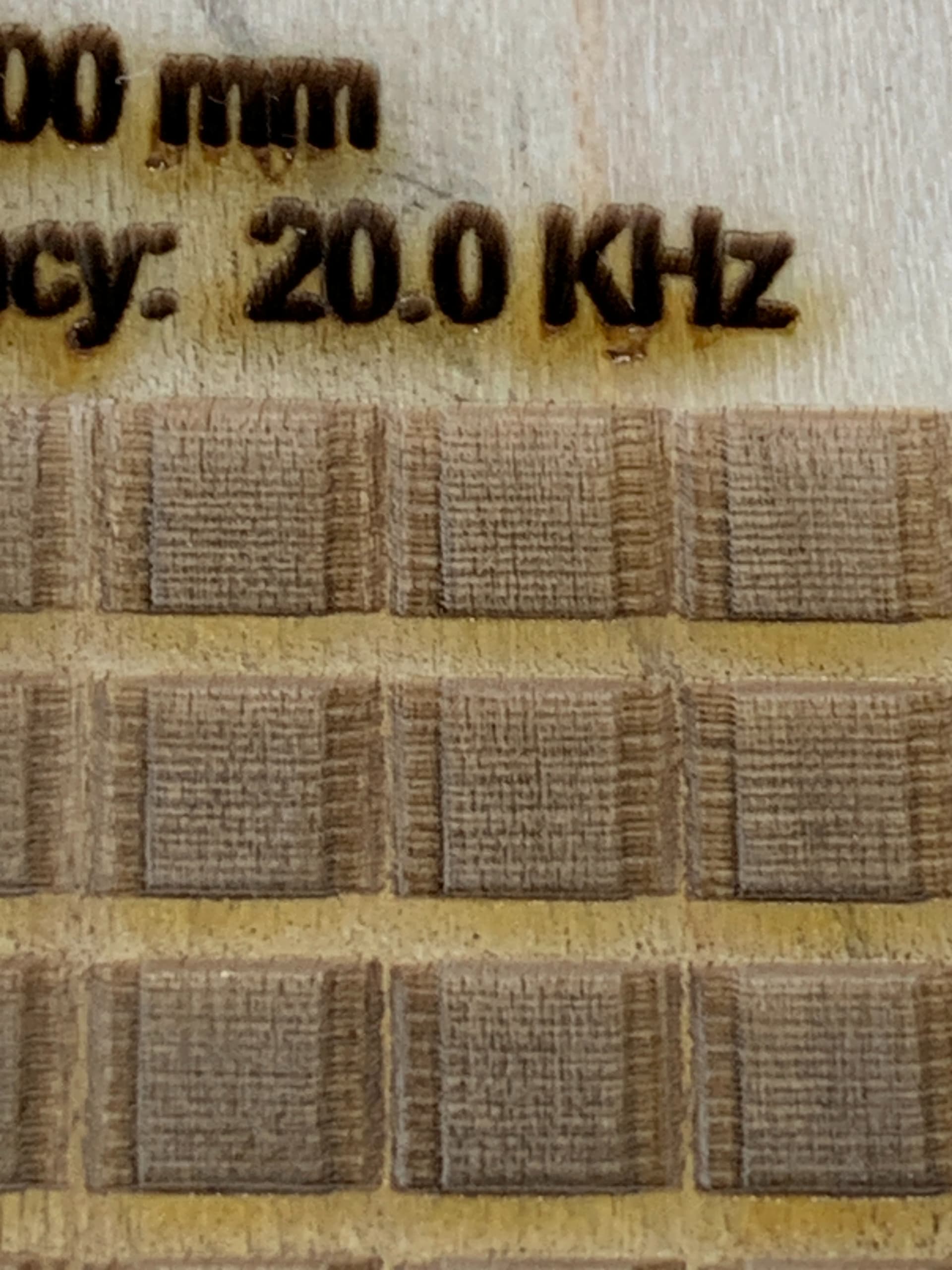
Has anyone experienced this? I’m realizing now that I have a closeup view, it seems to look like a ramp on the extents of the X axis, however this was a grid generated from the material test generator and I checked the ramp length and it shows 0.00 so from what I read, that should mean no ramp. I’m also noticing that the land between the squares gets smaller and smaller as I go higher up the scale (faster as I go up). At the bottom I’m at 40mm/sec at the top I reach 550 which to my knowledge is nearing the extent of the machine.
I must have accidentally used Fill Shapes Individually, hence the reason it is on each individual square, regardless, it would do the same thing just all around the outer edges on the image.
My machine tends to rock quite a bit at these higher speeds, is this normal? I’m wondering if this is having an affect on it. There is a carpet/padding/subfloor underneath which I think might be contributing to the sway. I plan to put a metal plate beneath in hopes of stabilizing it.
I can see the offset lines in the output at higher… which is why they look closer to each other…
All machines have some clearance that is required for it to operate. When you increase speed this clearance issue causes the clearance to be more visible…
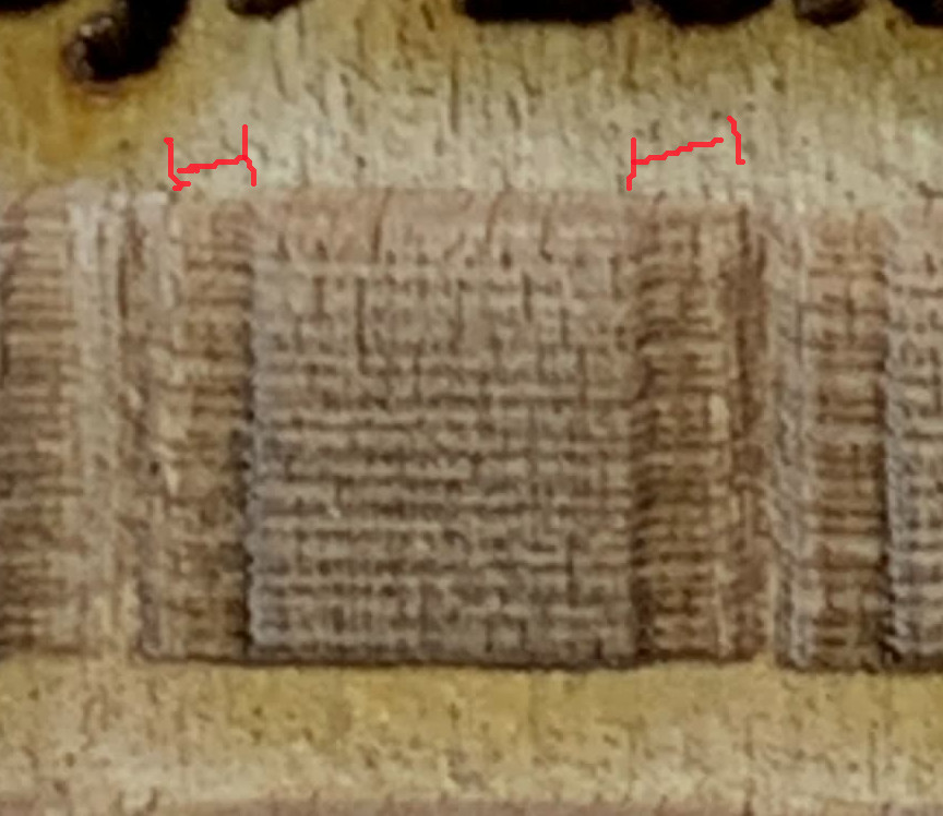
You have cut off the speeds from the image… but I can see it in the output… I’ve marked it in this copy of your image…
OK thanks Jack, so this is normal then. The top one was 550mm/sec.
I’m not familiar with line interval, but I’m not 100% through the manual so I will likely come across it soon. Can you advise what you mean by this?
It’s how close the tool paths are to each other when a fill or dither is used.
When you lase a filled box, the head moves back and forth… With the head, usually scanning left to right, but scanning … The line per inch or dots per inch are used to tell the machine how much the Y axes can move when it does the next line…
Line/inch related directly to dot/inch.
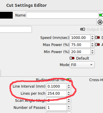
If the beam is 0.1mm, the best coverage will be 0.1mm/inch or 254 dots/inch. If I make that 0.05 then the dots/inch is 508dpi. It has a profound effect on the resultants. I suggest you try it on some scrap material… Use something large so you can see the results.
Some machines run higher dpi than they can really accomplish… You get overlap of the beam on the material…