I have a time delay relay attached to the CN5 pin3 port on my 6442. It controls my exhaust fan for 45 seconds after the last laser pulse. If I want to control my new dual tube machine with a single time delay relay can I wire the two outputs together, and then connect them to the relay? Or will this backfeed into each output and cause issues. If not what would be the correct way to automate the exhaust fan? Thanks in advance
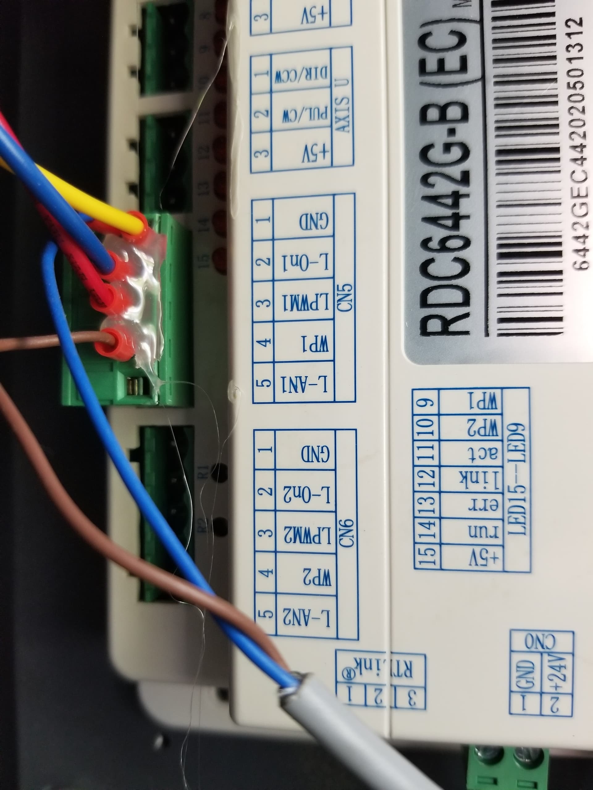
Yes that is the same board that I have.
Should be using the ‘Status’ I think. It will sink current when it starts.
Generally if it’s a ‘wired or’ you can wire them up together. There’s really only an issue if anything actively pulls the connection high. Most of these inputs get pulled low for active, but it’s configurable within the Ruida controller. The outputs also sink current or pull them low for an active.
You probably need to supply us with more information about the delay device and how it’s wired.
Do you have two separate machine you want linked together?
I know I can tap into the status out pin and run the fan during the entire job. But I like the control I get from getting a signal per laser pulse. If I need to walk away from the machine I can easily pause it and the fan will stop running shortly after I leave then start back up after I press start again. Since I have 2 laser out signals with the 6445 board for two tubes I’d like to be able to control the fan with either output. I’m using a DROK time delay relay board from amazon. I hope this makes sense with what I’m trying to do. Here’s a link to the relay im using.
I will say with my 6442 board I have the relay wired to lpwm-1 and gnd. It works great, the only issue I have is it runs the fan for 45 seconds on start up, and runs when I frame.
Do you have 2 tubes in your machine?
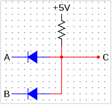
This is probably the best approach. A and B go to the LPWM connections and C is the delay module trigger. You will probably need the pullup resistors to 24v to ensure the diodes conduct. This is usually done within the controller, but the diodes isolate it.
What the diode are for, is if you have two tubes, you don’t want them both going off at the same time it isolates the LPWM for each tube.
Have you checked the LPWM2 to see if it’s active. Mine isn’t unless I configure it to be.
I’ve never heard of using the Lpwm laser controls the way you have. I don’t know if they have any kind of current limit. Most of the ‘sink’ ouputs of the Ruida are limited to 300 ma (depending on the documentation. You delay looks as if it’s just triggered by the transition, not really driving anything or drawing current.
Hope this helps… Good luck 
Yeah it’s kind of a different approach to it. I guess it feels more efficient, and ensures the smoke gets removed anytime the laser pulses. I have received my new machine, but haven’t turned it on yet. I went with the omtech 130w dual head 35x51. I’m coming from a 7 year old x700 clone. I’m currently in the process of getting the new shop space set up. I appreciate the advice, I’ll look into adding the diodes.
As long as you understand what’s going on. I’m not there but if you understand what I stated then you should be good to go. Be nice to have something with that much area. I have a a China Blue with a supposedly 50 watt tube. It’s 880mm so it’s a 40 to 45 watt tube. Had a great time with it…
Take care good luck…
Jack
1 Like
For sure, the diagram was nice too. I started with a k40 had a fun time learning the way of the laser with it, then got the x700 and have thoroughly enjoyed the 60 watts and the 700x500 work area. Now I’m going to be getting into production work with the dual 130. Solid advice Jack! Keep building and you never know what can happen.
This topic was automatically closed 30 days after the last reply. New replies are no longer allowed.