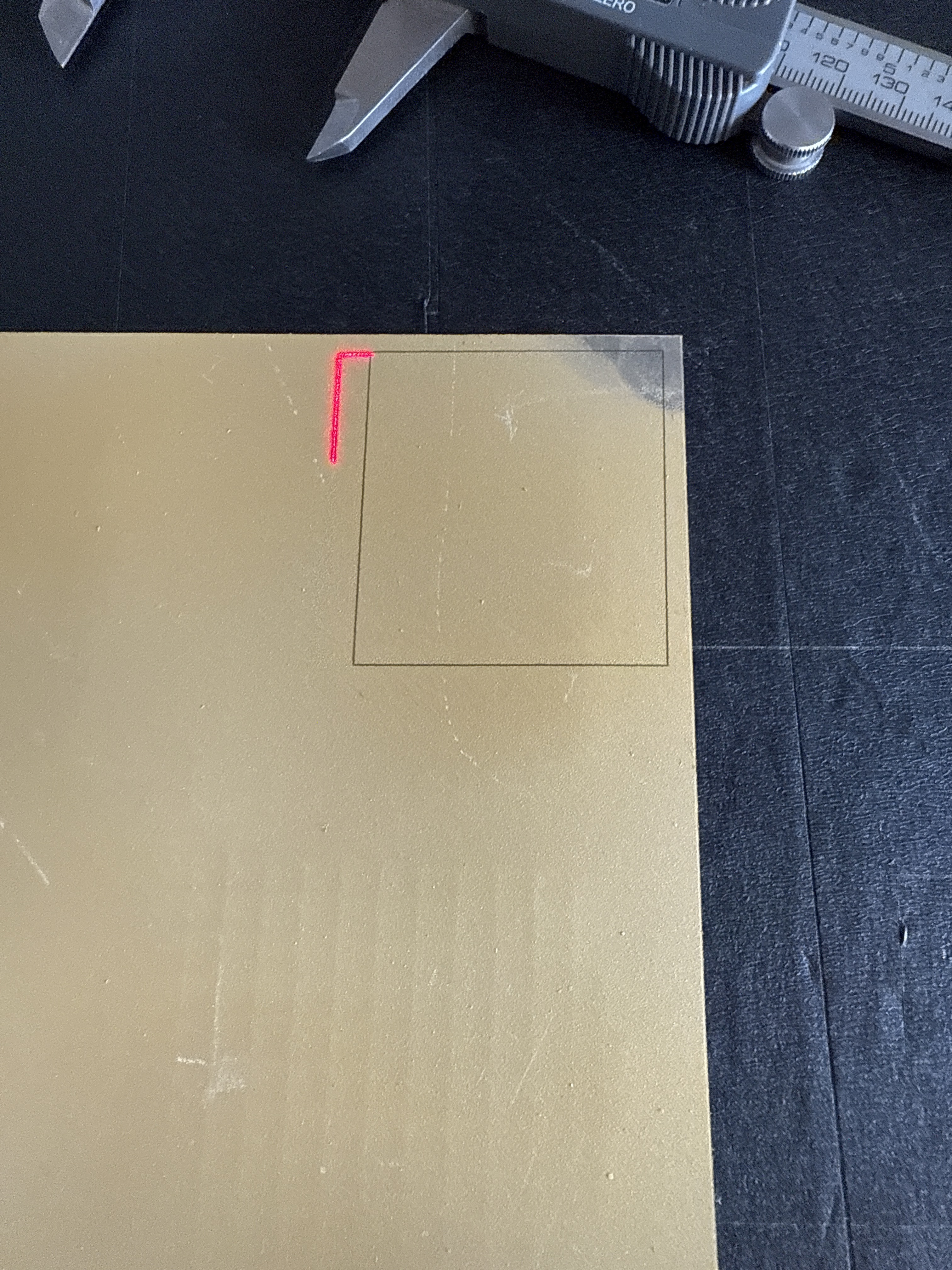
Sides and top were good but bottom of the burn is 5mm short.
So you are still going at it backwards, you need to be able to burn an accurate representation of what is on the screen before you worry about redlight framing. Run scale or 9 point correction or manually adjust your X and Y scale and get that right first. Otherwise you are wasting your time.
if your ton toff timing is wrong, it can shift the burn and the amount will vary with speed. that could cause variable misalignment
i did have this before working out the timing
OP is off by 5mm, not amounts you are talkng about. We need to get him plumb level square before we worry about timing.
agree. i only mention it because i got confused with my pcb etching on the mopa. i did Offset Fill first to isolate the bulk of the copper to be removed, then rastered that bulk with a small inward offset to avoid touching the trace. but at high speed, the raster has an offset different than the Offset Fill.
and it cut outside the line indicated in red dot framing. not by 5mm, though
By George, I think I finally got it through my thick skull. You happened to say it in the correct order that I could comprehend. Adjust the burn in galvo then adjust the red light framing. You probably said before but it just didn’t click.
Thank you for your help and patience.
No problem. This happens a lot, believe it or not. Onwards!
2 Likes
My TCON is about +125us. 300us seems high
I don’t see the engrave speed, but his JUMP SPEED is 4000mm/s
an extra 200us at 4000mm/s would be 0.8mm.
This would only stretch it if it was a raster, in the raster dir. This is a vector, and looks plenty large enough to reach constant velocity, so timing won’t change the spacing of the sides. It just messes with the corners. It could round off 3 of the 4 corners, or wait longer than needed to come to a full stop before taking off in the other direction, so it would overburn
That might as well be Greek but thank you. It seems to be working ok.
Yes, Danny talks to kindergarten students about quantum physics in his spare time.
1 Like
Forget raster (fill/image) for the time being.
Vector a rectangle and adjust red pointer scale/offset to make it fit before doing anything else.
Timing will shift a raster around along its raster direction. You don’t want to involve timing issues here.
Vector will go wonky on the corners if the timing params are bad. Overshoot, rounding of corners. But it won’t affect the bulk of the sides.
First, vector mark a large rectangle and measure the straight part of the sides, forget the corner. Use any difference between actual cut size vs the design to fix the scale in LB.
Note that if you raise the Z, everything expands on the workpiece in a nonlinear fashion- the center does not enlarge but the margins do. If the part is large, it can be very significant even while it stays in focus. However, the expansion should affect red dot and fiber laser cut about the same so this does not easily explain the red dot lining up
There are some lens distortion cals, I don’t have experience checking those. My best feeling is to ignore them for now.
Then do what you’re doing- vector a rectangle of specific dimensions, then go into device calibration and offset/rescale the red dot trace outline to match up with the cut’s sides. Again, ignore the corners for now
1 Like
This topic was automatically closed 30 days after the last reply. New replies are no longer allowed.