Reduce image engraving time

Hello! Beginner here.

I recently acquired a Sculpfun S30 Pro 10W diode laser and I’m trying to engrave some images. I know diode laser are slow, but I was wondering if there is a way to reduce the engraving time for images somehow.

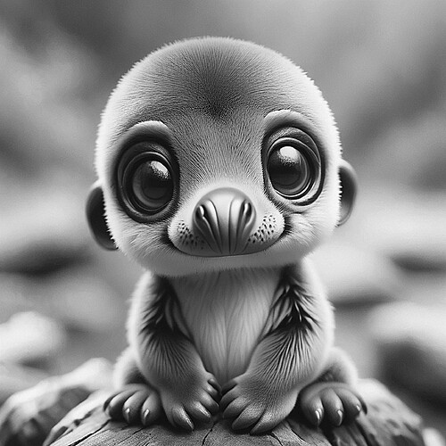
I’m trying to engrave this image (350x350mm) at 9500mm/min speed 30% power 400 DPI Norton Wood prepared in Imag-R. Lightburn is estimating 5h 40min, but in reality it takes even longer.
I modified the factory feed rate limits ($110 and $111) from 6000mm/min to 10.000mm/min, but I think, for some reason, it still doesn’t go over 6000mm/min. I notice the difference in speed for “classic” engraving, but I can’t seem to see it when engraving images.

Is there a way to reduce the engraving time because 6h is too much for me and I can’t afford it?

Thank you in advance!

With this image, the laser has to cover all of area at a 400dpi rate, it’s large so it’s going to take time.

Edit → Machine Settings usually gives you access to these limits. You might be able to increase acceleration, but I doubt it will buy you much.

Before you change anything, save a copy of these settings… some day you may need them… I save two, one locally and one on my Google drive.

I don’t run a diode much, so there are others that might be able to give you some suggestions…

Good luck — Love the image.

:smile_cat:

The image you attached is 677.3mm square. Use an image editor to reduce the image size to 350 x 350mm.

This is not helping your case. It is said that human vision can only really discern differences between printed dots at less than 300dpi so setting your print resolution above that is unhelpful and increases engraving time. There is not a linear relationship between engrave (print) time and dot resolution but if you reduce your image resolution to 300dpi, you will see some reduction in engraving time.

Another resolution adjustment can be made on the basis of viewing distance. It is generally thought that the ideal viewing distance for an image should be 1.5 or 2x the image diagonal. Unless you are making fine art quality image prints for a very high quality publication, you could assume 1.5x the diagonal length of the image.

The diagonal of a 350mm square is 495mm, which at 1.5x would be 742.5mm (29.23 inches) If 24 inches required a 300dpi resolution then 3.3 feet would let you use 180dpi for the same visual effect. It is likely using these numbers as an example that you could reduce the dpi to around 220dpi and not see any detrimental effects. This too would reduce your time but test engrave first!

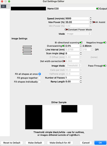
Your cut settings editor is set to simple black and white for a greyscale image. The software has to calculate values for the image tones which are not black or white. This requires some interpolation and may also be contributing to long cut times. There are grey scale settings in LightBurn and experimentation is required to find the best one. I reduced the image to 64 grey tones and it did not look great because some of the tonal information was missing. I suspect that you will need at least 256 grey tones to keep reasonable resolution in the image.

hope this helps

If he does this, it will change the interval.

I know he has it set for pass through … there is no processing of the image by Lightburn with pass through enabled.

:smile_cat:

When image processing for any purpose, I find it helpful to have 1:1 optimisation so that I can see a direct relationship between changes I make to the image file and the output. With pass through enabled, the interval and dpi settings are ignored.

Good catch. I missed that. My understanding was that when pass through is enabled, the image size is used to determine the dpi.

I cannot find it now but I recall reading at some point that pass through, when enabled, could slow down the engraving process.

I don’t know how it could do this very effectively… As far as I know there is no tangible relationship between image size and interval.

Saying that, when using a preprocessed image, such as from Imag-R, there is a need for Lightburn to know the interval. We normally think of resolution across the X axes, but it applies to both axes. Since interval is not accessible when pass though is enabled, Lightburn needs to know the interval to step the Y axes the proper amount… I’m speculating here, but it seems to fit…

This thread discusses it… maybe this is where you saw that image size determines dpi. Always possible that I didn’t read it correctly :thinking:

I don’t know how this works internally… but I know if I have to execute more code, it takes time… I wouldn’t think just passing a threshold image would slow it down. This happens so fast anyway…

:smile_cat:

Setting the values for interval without pass through being enabled will of course change the interval settings. The image will have been taken into LightBurn with its own pre-defined dpi; on being saved from any image editor. I cannot say if this pre-defined dpi is actually used to work out the interval settings when pass through is enabled.

You have correctly identified the thread where I read about the enabled pass through computing the image dpi based upon its size. I think this was the reason I felt somewhat intuitively that a more accurately sized image (350mm square instead of 677mm square) would give the software less work to do insofar as the coding required and thereby would shorten the processing time for @alalone’s image. I guess that @LightBurn would be able to answer that question more fully.

Yes, that is correct.

My understanding is that setting dpi values cannot affect the image with pass through enabled.

Yup, the overhead for processing the code cannot be escaped. I take the overhead to be computation time, excess computation time, indirect computation time, computer bandwith, computer memory and access time and any external resources which permit the software to run effectively, like the laser for example.

This is beyond my pay grade. :grin:

400 DPI is overkill, and not likely possible with the diode you’re using. 318 is possible, but that’s assuming really good clean optics.

One of the larger limiting factors with GCode based machines is the way the firmware handles the code and motion planning.

GCode controllers have settings for acceleration and max speed. If you tell the controller to run at 9000 mm/min (150 mm/sec) it takes it some amount of time to get up to that speed, and the same amount of time to slow back down again.

If you draw a simple rectangle, there are basically 5 GCode instructions:

  • Move to the first point
  • Laser to the second point
  • Laser to the third point
  • Laser to the fourth point
  • Laser back to the first point

Each of those points is a sharp corner, so the laser has to slow down basically to a full stop, change direction, speed up again on the next line, and so on. The speed curve for one of those sides might look like the blue line shown here:
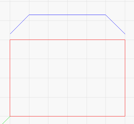
image

Internally, the controller puts all the GCode moves into a buffer called the plan buffer, so it knows what’s coming and can move accordingly.

If you’re driving on a flat highway in broad daylight with great visibility, you’d probably drive much faster than if it was pitch black out and raining, because you can see a lot further, and can see upcoming turns and hazards more easily. You usually drive at a speed that gives you time to stop if something pops into view.

The laser works the same way, and the planning buffer is how it does it. That buffer contains a bunch of upcoming moves, and the controller goes through them to figure out when the corners are coming, so it doesn’t go so fast it can’t stop in time.

Images end up being lots of very short moves in the planning buffer, and the buffer is not very long - usually about 32 moves, maybe a bit more depending on the controller.

400 DPI means each GCode instruction could be as short as 0.0635mm. 32 of those back to back is just a touch over 2mm. It’s very likely that your laser will need more than 2mm to get up to 150 mm/sec, but since that’s as far ahead as it can “see”, it has to limit the speed to however fast it ends up after 2mm of acceleration.

If it goes any faster, and the next move added to the buffer is a full stop, it wouldn’t be able to stop in time.

In practice, the shading ends up giving some spots that have longer dots or spaces, so in those parts the laser can see a little further ahead, and will run faster, but when you hit parts of the GCode that are just lots of tiny little dots, it has to slow down again.

If you can post your $$ settings for the controller you have, and post what it says when you type $I (info), I could tell you how big a planning buffer you have, and how far ahead your machine can see.
4 Likes

This was a nice clear explanation of the issue. Thank you. :grinning:

The S30 Pro is a superb machine without diddling with the parameters. Like someone mentioned above, you can’t cheat physics. Maybe you can make it whip around faster, but precision will suffer. The only thing I think you can do to the S30 Pro is increase the acceleration rate that may have some effect.

But to be honest, 6 hours for a 14" square image is not that bad. If you really need blazingly fast, buy a galvo machine.

By the way, that image is pretty darn good! I was surprised to see 6000+mm/m at 30% power gave such good results. I may have to revisit doing tiles.

1 Like

At the risk of getting blacklisted, I am going to say this part barely applies here.

Raster scan

  1. Line 2: starting in the overscan zone, it accelerates to set speed.
  2. Crosses the image at the set speed. May speed up if not at max speed and Skip White Zone selected.
  3. Decelerates at the overscan zone and stops.

There are two speed-ups (2.5% overscan) for each line, being the main place where any improvement can be made. It appears little can be done for this image with little whitespace and max speed.

A 5% time improvement would only be 18 minutes.

I was illustrating the difference between a simple rectangle and an image.

With a rectangle, you’re right, the laser can see very far ahead and so the process is trivial. For an image, since the system can’t see far enough ahead, it has to go slower than its allowed maximum.

4 Likes

Most people do not comprehend this is how it has to work.

Speaking of work, I am keeping you from it with my distractions. Thanks for responding!

Thank you guys for your answers, especially @LightBurn for the detailed explanation and sorry for the delay!

Here is my $$ and $I as requested by @LightBurn:

$$
$0=10
$1=25
$2=0
$3=4
$4=0
$5=1
$6=0
$10=1
$11=0.010
$12=0.002
$13=0
$20=0
$21=1
$22=1
$23=7
$24=200.000
$25=3000.000
$26=250.000
$27=2.000
$30=1000.000
$31=0.000
$32=1
$41=0.000
$40=0.000
$100=80.000
$101=80.000
$102=250.000
$103=100.000
$104=100.000
$105=100.000
$110=10000.000
$111=10000.000
$112=1000.000
$113=1000.000
$114=1000.000
$115=1000.000
$120=2000.000
$121=1000.000
$122=1000.000
$123=200.000
$124=200.000
$125=200.000
$130=410.000
$131=400.000
$132=200.000
$133=300.000
$134=300.000
$135=300.000
$i
[VER:1.1h.20230903:]
[OPT:V,15,128]
Target buffer size found

I think I maybe created a confusion about the image in the original post. That image is not the final engraved image. It is the original that I created with AI. Sorry for that.

Another addition to what Jason already mentioned: physical limits of the mechanics is one thing (as he explained above) and the second thing is the limit of data transfer. If you have those images with many short instructions, not only the internal buffer is filled very fast, but all those instructions have to be transferred to the laser. We had some threads here where it was discussed in more detail, but the bottom line is: If you have a 254 DPI image where every pixel is a new instruction, you end up with 6000-7000 mm/min being the absolute maximum speed at which data can be transferred at a baud rate of 115,200 (ignoring the mechanical limitations). Since your DPI are higher, the maximum data rate will be even lower.

[OPT:V,15,128]

This says that your “look ahead” buffer is only 15 moves, which is unfortunate. The “character receive” buffer is 128 bytes, but that’s not relevant to motion planning.

Your acceleration values for X and Y are 1000 mm/sec^2, which is relatively slow, but normal for a diode with a heavy laser head.

At 1000 mm/sec^2 acceleration, it takes 0.1 seconds to fully stop from 100 mm/sec, and in the time it takes to stop you would travel 5mm. If you are using a 0.1mm interval, your laser, with a 15 move buffer, can only see 1.5mm ahead. It looks like your limit is about 3240 mm/min at 254 DPI. Meaning that you should expect to see your laser drop to that speed when the shading is lots of runs of single dots.

1 Like

Does this mean that I should get the most accurate and “crystal” engravings with these settings?

Not at all. The calculations Jason posted were regarding the speed of the movement. The speeds have nothing to do with the sharpness /accuracy of the result (ok, not exactly, incorrect speeds / movements will also lead to the mechanics not following correctly). To get the best results in terms of image quality, you need to consider your laser characteristics. The main thing here will be the size / shape of your laser spot. You need to tune the DPI setting / line width and height to the size of your laser spot. So if you set to 254 DPI, that means you have a line interval of 0.1mm. If your spot is bigger/smaller, this won’t give best results.

1 Like

This topic was automatically closed 30 days after the last reply. New replies are no longer allowed.