Reducing co2 laser power further?

You got the jist of my problem. Doing small line (not raster) fonts can only be done relatively slowly because there are lots of course changes in a small space. I know about the power variation made by Ruida/Lightburn during course changes of the laser head and the slight variability of the laser turn-off point (I think it’s temperature dependent, both ambient and probably of the chinese LPS too).

Yes, I have some electronics and engineering knowledge and equipment. I also have a MAmeter waiting to be installed.
I am away from the machine the next few days, so can’t test anything right now.

Maybe I can solve all this as is, but compared to a diode laser the Co2 seems much less controllable at low power, so some kind of filter to dim it down a bit might still be in order. Or maybe I can just shine it through a smaller hole in a metal plate somewhere before the 1st mirror.

Yes, one is a solid state devices that has known states at certain voltages. The co2 is based on temperature, gas mixture and response time of the lps. You are right there is little control at the low end compared to a solid state or even an rf excited tube.

However, something is seriously wrong when you can’t just ‘mark’ paper. I would find that issue instead of attenuating the beam.

:smile_cat:

Will do when I get back, thanks.

“START SPEED” is where the laser will start going above MIN POWER. If MIN POWER is set to a high number, you can still get a beam.

If I set START SPEED to 10mm/s, MAX POWER 100%, MIN POWER 15%, and then ask for a vector cut @ 100% MAX POWER:

  1. Say your Layer ask for 40mm/s cut speed. at the start and stop or corners where it slows below 40mm/s but above 10mm/s, it will scale back the power according to the ratio of actual vs commanded speed. As best I understand it, 10mm/s would be 15% PWM and 40mm/s would be 100% PWM.
  2. With the same scenario, when the axes are near start/stop/cornering and at 10mm/s or below, the output will be a fixed 15% PWM.
  3. If you instead set the Layer to do a 5mm/s cut, then it never hits that 10mm/s START SPEED, so the output will be stuck at 15% PWM.

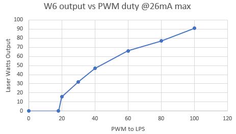
I did readings with a Coherent thermopile power meter that gives accurate, live readings for the included chart on a Reci W6. It’s still basically linear relationship, watts=(PWM% * 91W), but clips below 20%. This is NOT an offset for the zero- it’s not 0W at 20% and ramps up linear from there. The tube can’t put out a stable 10W no matter what the PWM duty.

pwm_vs_output

The ideal cut would be a constant exposure of joules/mm as it slows to start/stops/corner. If our 100% PWM is 91W and we want 10mm/s, that target is 9.1J/mm across any instantaneous speed.

I don’t see any reason for the START SPEED to exist. This is a bit confusing, pay attention to what’s a %PWM vs %power output. With no START SPEED (1=none, more or less), when it’s commanded for 10mm/s MAX POWER 100% but instantaneous speed, we want half the wattage, so 50% PWM will basically produce half the wattage out. Because it’s still linear and centered on 0. At 20% PWM, I measured about 16W but as I continued to fire at that PWM, the beam output dropped notably as I kept going. Below 15% PWM, we won’t really have a beam from the W6, so all we can do is leave it at 15% PWM and get like 15W out of 91W. At the very start, say 1mm/sec, we’re at 15% PWM,15W, but 150J/mm because turning the tube any lower will drop the exposure to 0J/mm. Note this is all MIN POWER lower PWM limit, not START SPEED. That’s pure linear “velocity scaling”.

But if we add START SPEED 10mm/sec, it’s saying to always use MIN POWER below this speed. I’m a little uncertain on how velocity scaling actually calculates its proportions, but this is what I think. That SS=10mm/s now means there’s no linear velocity scaling, it’s always at 15% PWM 15W tube output. So at 5mm/s, instead of the ideal 9.1J/mm- which is entirely possible to do- it’s going to underdeliver 15W at 5mm/s=3J/mm.

If we ask for 100mm/s with SS=10mm/s, this is only going to be below the SS for a very short distance around the start/stop/cornering points. But still when SS does kick in, well it’s just breaking the J/mm exposure ratio.

On the other hand, if you want to cut thick acrylic and command 100% PWM @ 5mm/s with a 10mm/s Start Speed, then we’re cutting back to MIN POWER for absolutely no reason and breaking the J/mm exposure entirely. We asked for 18.2J/mm, and it would do that with no SS, but if we have a 10mm/s SS then it will underdeliver the beam to 15% PWM = 15W= 3J/mm.

That’s my understanding. SS is just bad math and should be set to 1 to get it as close to “off” as possible. I speculated that SS was created to prevent users from accidentally specifying what might be destructive, like 100% PWM at 0.1mm/s=91J/mm. Maybe that would erode the honeycomb itself. But that’s not up to the Ruida to intervene, and it’s not taking into account the commanded MAX POWER. Maybe my MP is only 10% anyways, that’d be back to 9.1J/mm.

And that scenario came up with Norton White Tile, which seems to only fuse at 20mm/s and very low power. The machine had a SS=15mm/s, I tried to run a test at 10mm/s with the PSU’s analog current pot turned way down and asked for a PWM of 30%. Well that is below the machine’s SS, so that dumb SS limit took over and throttled the PWM to MIN POWER =15% for no reason.

I’ve never seen a commercial product with a setting (in multiple places) that had no use. It’s very possible that it has uses outside of the laser field as these seem to be used in all kind of cnc equipment.

I think I follow your description, but I can’ make it work anyway I try it. Using the simple example I spoke about.

Oz mentioned that it’s the start speed, but neither seems to work as it’s explained or I understand.

I think I’ve come to the conclusion I’ll never completely understand how they work and will have to just live with it.

:smile_cat:

I have a suggestion that may help. I have a 130w laser and for me to get the marks you are looking for I have to use a mask. I set the minimum at 6.5% and the max at 8-10% depending on what I’m marking. 6.5% is where my laser stops making a mark. I set the speed to 35-50mm/s depending on the material. The mask takes up most of the energy and I get a very light mark on the material. Unfortunately, I still occasionally get piercing on the corners so i try not to have sharp corners, I will try and radius them as much as I can get away with. Good luck and I hope you sort out your problem.:+1:

1 Like

Speed it up go like 400 mm/s

There is a ton of these machines out there, no one is trying to ‘lower’ the power.

There is a problem and it’s indicative of a message to you that it’s going to fail. Lights burn the brightest before they fail…

You need to identify what is causing this excessive power output, not try to lower it by external means.

I cut and mark paper all the time at very low power as do many with these lasers. You need to find what’s causing this.

I think it’s telegraphing you that it’s got a problem. Until you fix this issue, it’s going to be a problem.

Have you checked the your beam for the proper resonance? A shot of the beam mark at m1 would ensure it’s operating in TEM0

Good luck

:smile_cat:

What does this mean?

:smile_cat:

Thanks everyone for contributing so far!
Finally had a chance to play some more today:
Installed an ammeter. The minimum I can get before the laser stops working is about 3.5 to 4ma.
It is a 60W power supply running a 50W laser tube.
The maximum speed I dare use on the very small line (vector font?) font is 40mm/s. This is to mark the very soft wood of the plane kit, Japanese Cedar, similar to a medium balsa wood, before cutting.
It still cuts the letters too deep, about 0.5mm, weakening the structure of the aeroplane. Monday I will try de-focusing it and doing the marking stage separately to the cutting stage on Lightburn.

If you can’t reduce the power, can you speed up the head? That will put less laser power on a particular point.

No, It’s a very small 3mm high line font and the head can’t change course too quick. There are also lots of sharp angles so high speeds are out of the question. This isn’t raster scanning, it’s all vectors.

I havnt got much experience compared to everyone else here, but what about simply layering your project with masking tape or cardboard until it is thick enough to allow the laser to simply mark instead of cut?

It’s not really feasable. I am making plane kits for a club and it will be quite a lot.
I managed to improve things slightly by fine tuning the minimum power but on such small and light indoor (sports centre hall) planes which use sheet that’s only 1.6mm thick, any rduction in thickness weakens the stucture.
I have still not given up on marking yet. I want to find some tinted glass to put in front of the 1st mirror or try firing the laser through a small hole in a piece of metal to reduce the cross section.
If all that fails then I could mount a diode laser instead, just for marking. I suppose I could even mount the laser diode in front of the third mirror?

I’m wondering if using perforation mode on the text would help. At least it wouldn’t weaken the material as much and you would probably still be able to read the text.

You could convert the vector to an ‘image’ and ‘scan’ it at a higher rate. A higher dpi might improve looks.

I run in that area quite a bit. But it really depends on the power setting, and if pulsed, how long.


IMHO, I think you have the original ‘some kind of problem’. There are lots of people with these machines that can easily a small vector graphic on paper… I do when making targets.

Now that you have a meter, I would do a continuous pulse at 50% power to get a stable mA meter reading and that will tell you how much current the supply is capable of. My machine has the same combination of 50watt tube/60 watt lps, I had to turn mine down to stay under the specified maximum current limit.

Mine is actually a 44watt tube, measured…

This just seems all wrong for such a common machine… and my only thought is to try what you are doing on another machine.

I don’t have any thin balsa to try some of your code and see if I had the same issue… Maybe someone else with a similar machine/material can give it try …

:smile_cat:

One option would be to replace one of your mirrors with a less reflective one.

AliExpress used to sell “20mm 10600nm CO2 Laser ZnSe Output Coupler Partial Reflection Mirror Engraver 30%” (according to Google), but I can’t find stores with current stock.

Based on limited research, I’d suggest searching for “co2 output coupler”. That seems to be the terminology for a partially reflective mirror.

What happens to the unreflected part of the beam is another concern, of course. You’d want to be extra safety conscious with additional beam components wafting around in your machine.

If it’s not reflected, it’s absorbed and ends up heat.

:smile_cat:

Hello again, I have been sidetracked with other stuff but back again.
Yes, I am wondering whether a beam splitter might also be effective at reducing the power? I will look for all the previously mentioned items, thanks!

Have you tried turning off the air when you engrave ? The turn air back on for cut.