I use a CAD Software for my 3D project. So I build them in a 3D environment, generate a drawing and export it as a DXF-File. That is what the CAD Software offers me. Within this 3D environment it is not allowed to have simple drawn lines. I always need closed forms there.
So I want to cut out wood that can be bent. It works.
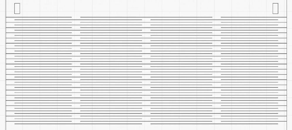
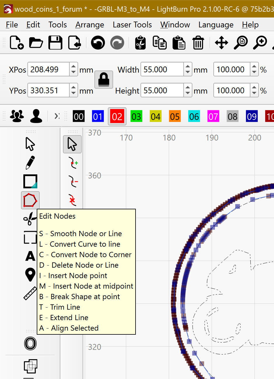
What I want to improve: It is not lines, it is small rectangles, therefor my cutter runs over this line twice.
The rectangle has some lenght, let’s say 50 mm and 0,1 mm thickness.
My ways so far:
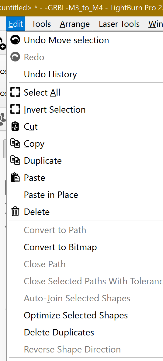
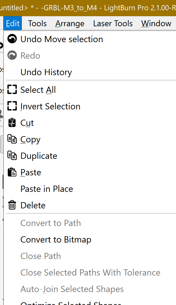
edit → find doubles (what they are not),
edit → optimize forms (finds only few of them!!!)
laser → remove overlapping lines (what they seem not to be)
Is it possible with this software? I would need some help to do it, as I cannot figure it out on my own. Here ist the example how it looks like: The horizontal lines, are not lines at all, it is
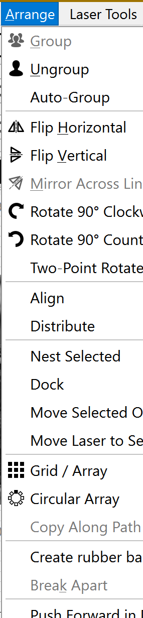
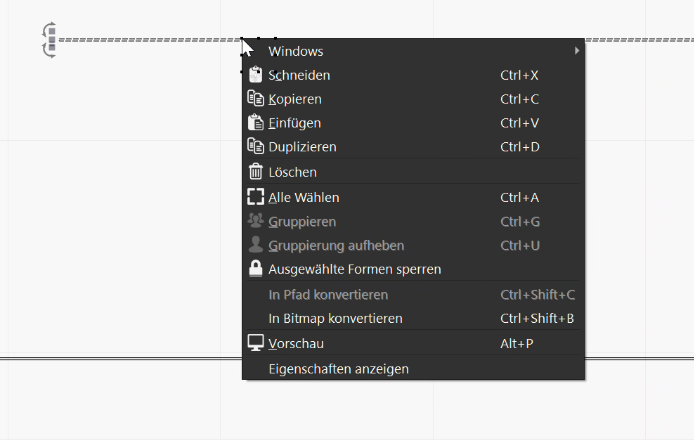
And thank you for your quick answer. I found your suggested solution, but I forgot to list my efforts on it. I cannot ungroup. It is greyed out… In this case it is only one rectangle marked. But I also tried with Mark All (STRG+A).
That sounds close enough to 10 cm interpreted as inches to suggest there’s a units mismatch in the path between the CAD layout and the LightBurn layout.
DXF files may or may not have units that may or may not be interpreted correctly, so verify the DXF import settings:
The Auto-detect units if possible option sometimes goes hilariously wrong.
For SVG files, the CAD export and LightBurn import scales match:
Generate a CAD layout of squares with obvious sizes (1 inch, 10 cm, whatever), export it into DXF and SVG files, and upload them here so we can see what’s going on.
Thank you very much for your help.
I did some more tries 2 weeks ago on this before I read your answer. But I will research it again somewhen next week as I have a lot of office-stuff at the moment and will come back to this then.