I want to replace my LU1-3 ( 12v) laser head, to a LU2-4 (24v) laser head.
Going from 12v to 24v, do I simply buy an Interface Driver Adapter Board? Am I correct assuming this board will accept my 12v and PWM signal and send out a 24v & PWM signal to my new 24v laser head? Am I on the right track???
What board are you referencing?
Partially correct. If you board will run off 24V that’s nice…
However, generally you’ll need the adapter to remove or separate the 12V, supplied by your current controller, to the laser module and in place, route 24V from another power adapter to the laser module.
The ground can pwm lines are common and are untouched… The 12V is generally ignored.
Make sense?
![]()
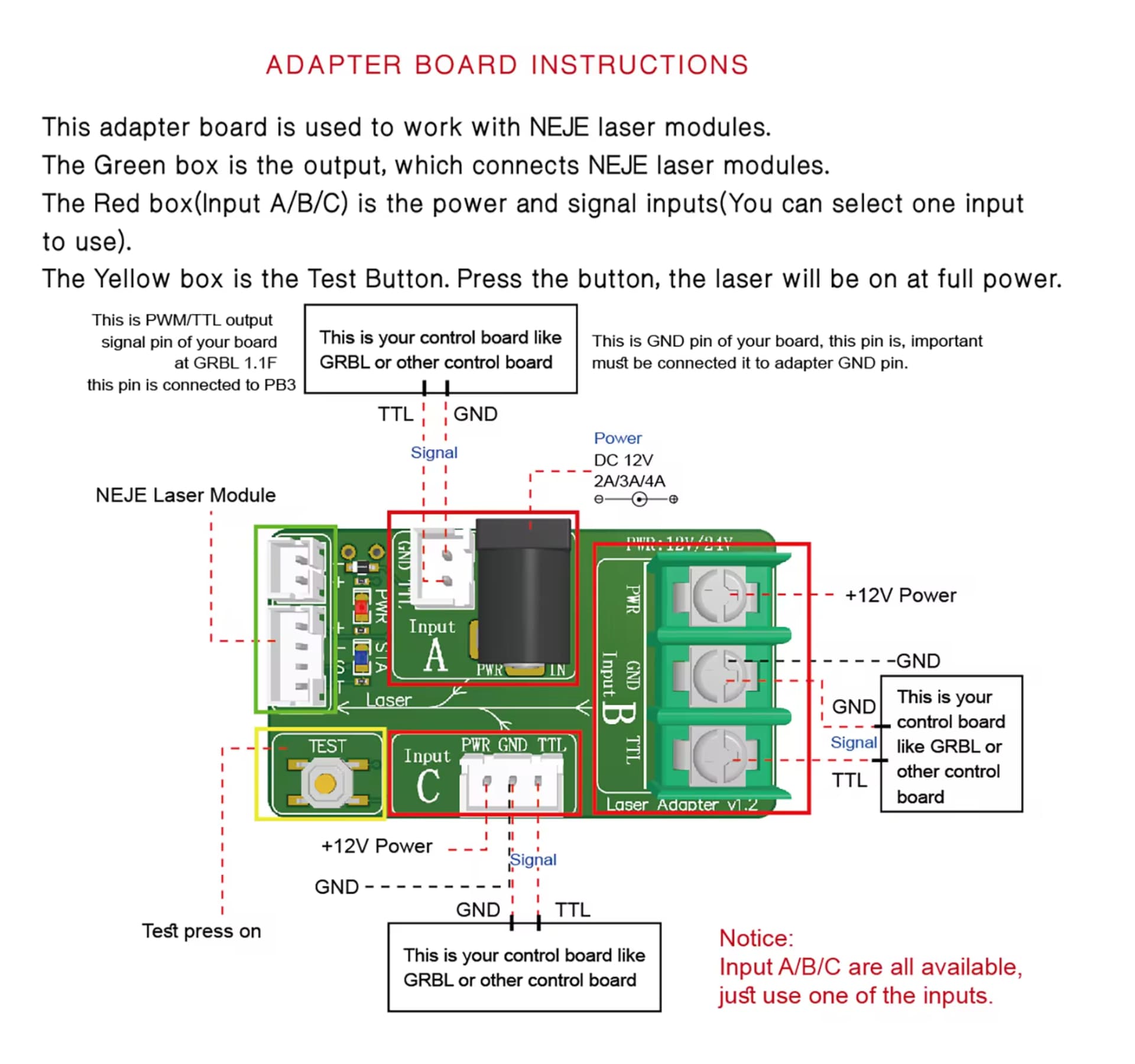
They are called “Interface Driver Adapter Boards”. They are placed between the laser controller board and the laser head. They input the 12v, GND & PWM from the laser conterller board, and output 24v, GND and PWM that then goes to the laser head. Seems pretty straight forward, but wanted someone to double check my thinking.
Here is another one…
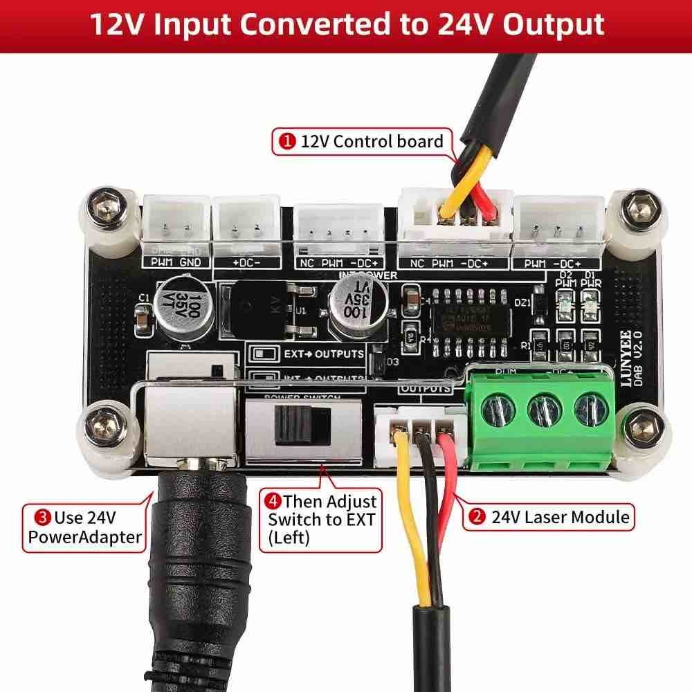
kinda. See what this “Interface board” looks like? I give it 24v via an external PS. It takes the 12v and PWM lines from the old controller. It ignores the 12v
and passes the PWM & 24v on to the laser head. ( I think )
This is the most complex interface board I’ve seen and I have no idea why it has so many active parts on it.
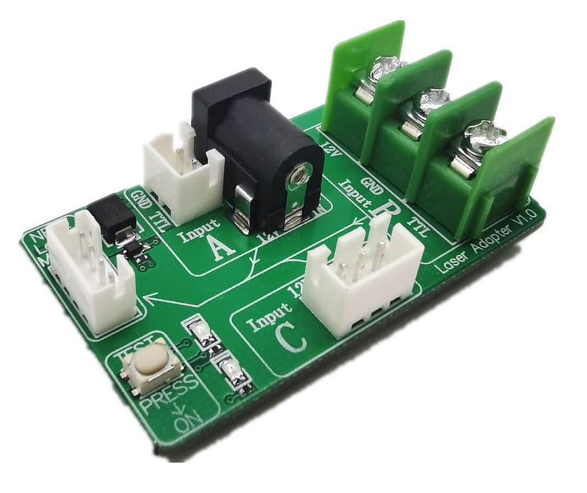
This is what mine looks like – it’s only got a couple diodes and leds on it.
I’m clueless about the switch setting… where did you get the photos?
You’ll need more information if these are not a factory supplied set to work with your laser… otherwise you’re just guessing while making a relatively expensive wager.
Ask the vendor for a more useful configuration of the board, including the switch settings.
Scotty:
The more they overthink the plumbing, the easier it is to stop up the drain.
BTY, you don’t need to duplicate them…
![]()
1 Like
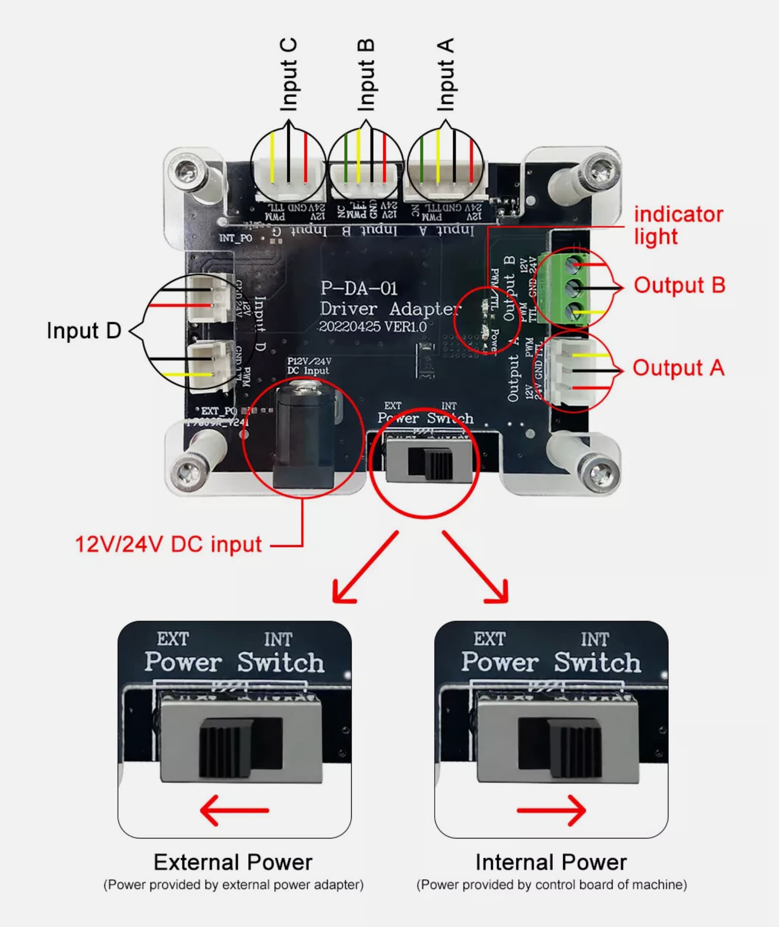
The switch allows you to select either passing the “internal” input voltage from the control board or to the “external” power via the power adapter.
1 Like
I thought the reason for the board was to isolate the two separate supply voltages?
Are you saying it can run the board with a single 24V supply from a single supply?
This has a lot more parts on it, so I’d be inclined to think it was doing more…
![]()
1 Like
I don’t think I’d describe the intention of the board about being isolating the supply voltages. The intention of the board is to help facilitate various controllers to interface with the supplied target laser module in order to widen the available target market.
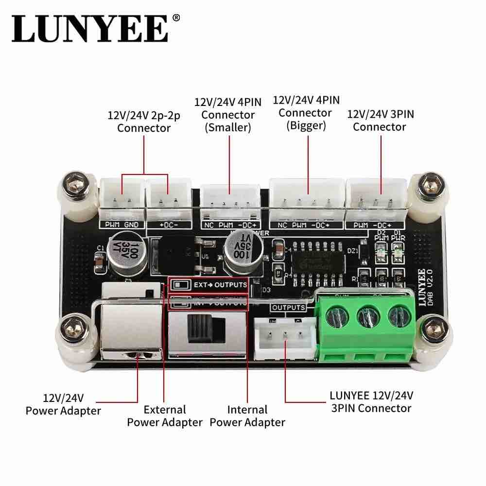
To this ends the board allows for various input types in terms of size and type of connector. It further allows for the variable selection of power source between what’s being passed from the controller or what’s plugged in through the external power source. It’s almost certain that the switch is mechanical so likely a hard separation of voltage being passed through.
While the power adapter plug is specified as 24V I suspect it will pass whatever voltage is provided by the plugged in power adapter. In practice, it would only ever make sense to plug-in 24V as that is what’s required by the laser module for proper function.
1 Like
I agree something simple…
That’s why I wonder when I see what looks like a voltage regulator, an IC and a couple of 100uF caps… seems excessive for such a simple operation?
I’m suspicious more is going on… My board has two diodes… that’s it.
Not an argument, just a discussion…
![]()
I do agree that there are surprisingly a lot of components on the board. I can’t make out the lettering but perhaps they’re for safety mechanisms. Purely speculating.
Your board is for a NeJe laser… I have an Ortur.
This board I showed here is for MANY different systems…
the board has 4 input connectors, you will only have to use one, the connector compatible with the connector that powers the old laser. by inserting the 24V power supply, and positioning the switch on EXT POWER, you will have the output of the new laser board powered at 24V. By positioning the switch on INT POWER SWITCH, you will have the output of the new laser board powered by the power supply of the old laser. The board is used to separate the laser power supply from the rest of the CNC. if during processing you notice that at a fixed working power of the laser, the intensity of the light varies based on the movement of the CNC motors, (to see, you must wear safety glasses certified for the working frequency of your laser, and I advise you not to look at the direct light, but only the reflection for the short time necessary to see the constant light) it means that the CNC machine power supply is too small, a board like this makes you power the laser with another energy source.