Some weeks ago my 100w Chinese 6040 laser developed a Y-Axis limit switch problem, evident from the loud grinding noise from the stepper motor on start-up and the lack of any indication from the LED on the hall effect sensor. I planned to replace the sensor today but saw that dealing with the cable ‘raceway’ (bolted from underneath) and insufficient length of the supplied cable were going to make it difficult to fit.
I also discovered that the problem was not the sensor itself but the cable; with an open circuit on the blue wire (probably somewhere along the cable raceway). It also got me thinking about mounting the new switch & cable assembly *on the main chassis rather than the carriage assembly, thus avoiding the need to route the cable through the raceway. I would then simply add a small iron bracket on the carriage to activate the hall effect switch. It seems a simple solution to me, but there again… why are the sensors usually mounted on moving carriages anyway? Is there something I’ve forgotten?
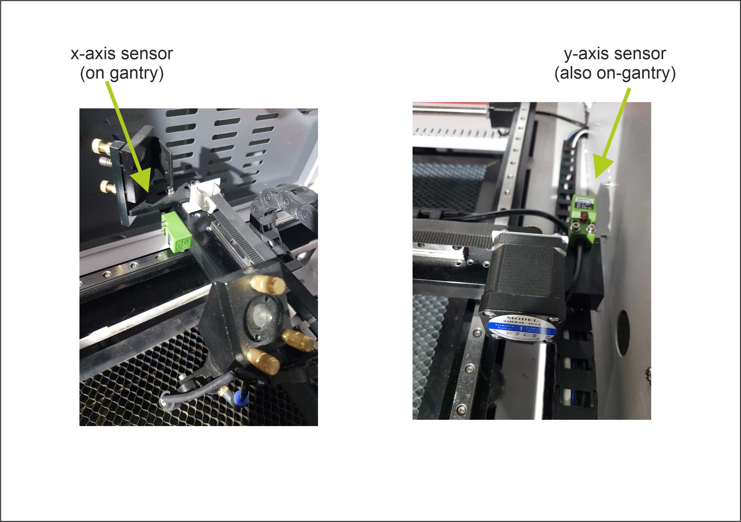
My y-axis sensor is mounted to the frame, with the metal plate attached to the gantry. I don’t know that the wiring for the sensor travels through the raceway.
The x-axis sensor has to be mounted on the gantry which requires the wiring to be placed in the raceway.
Perhaps the arrangement of your machine is different. Perhaps a photo or two?
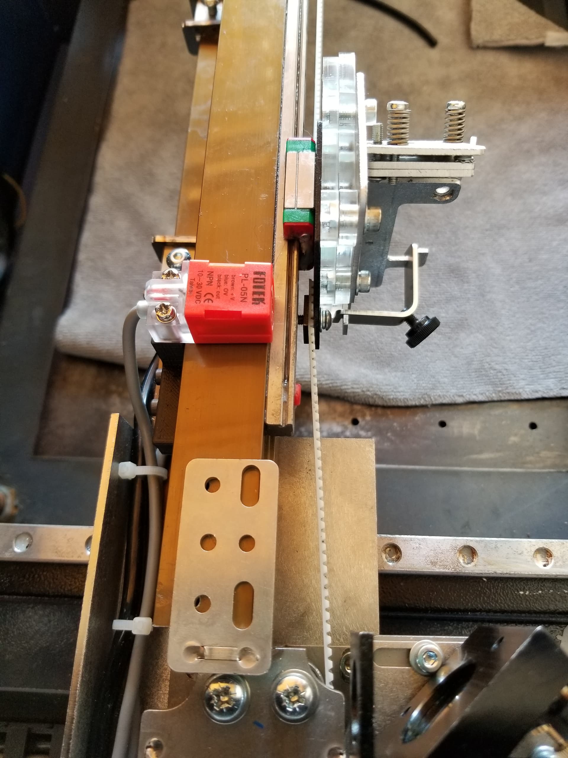
Here’s a Pic of the existing limit switch setup… The X-axis switch is on the gantry (as is understandable). My query is really about the Y - axis switch which is also the one I’m having trouble with. After I posted the original query, I did actually replace the switch with a new one (shown in the pic.), using the existing cable raceway, and… I have much the same failure! This is weird and I will investigate more tomorrow.
That’s a curious configuration. It does seem a bit peculiar to have the y sensor on the moving part. If you’re able to mount the sensor where the trigger plate resides and vice versa, you’d be able to remove one enclosed wire set, but there’s no way to get rid of both.
If you’re willing to make changes in the overall configuration, you could mount the x sensor on the other end (or turn the y sensor 90°) and change the travel direction and origin.
You can also test the sensors by starting the machine and bringing a metal object to the top of the sensor (side of the sensor for the x) to see if the machine will accept that as the new (temporary) zero. If it does, the wiring and sensor check out. You can also check the sensors without mounting them by connecting to the controller directly and use the metal test at power up.
If there is a broken line, changing the end part isn’t going to help. I’m assuming it also would not trigger with a screwdriver or other metallic item. That would indicate the the sensor was not getting power, probably the blue line.? Or did you actually replace the cable?
I had to move mine when I changed some parts. It was on the back of the x gantry, but that metal was gone so I had to move it to the top.
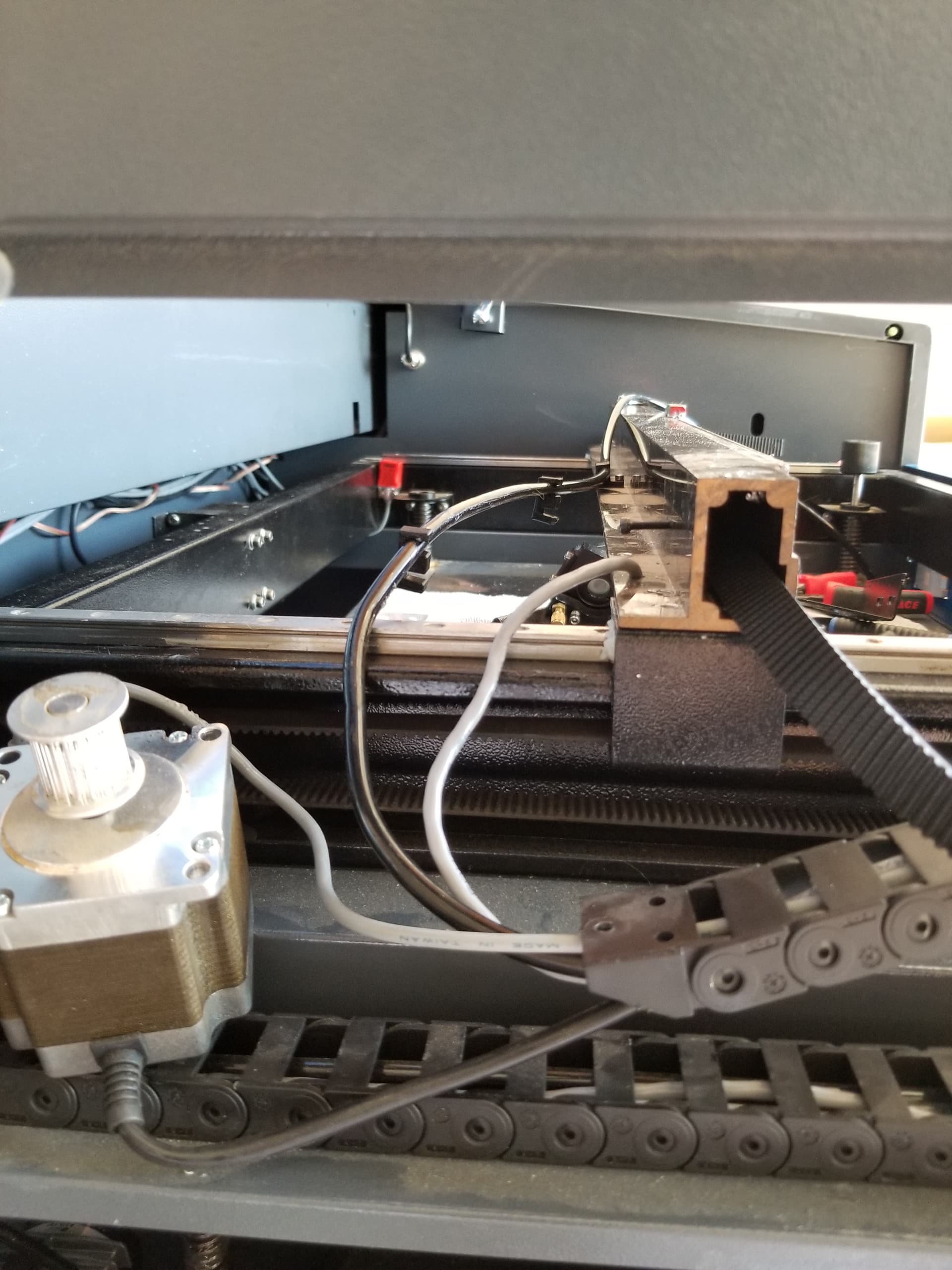
I think most of us that build or work on this stuff put anything unnecessary on a moving part. It’s wear, such as cables that there will be a failure. You can see the Y limit, on the far side, in this photo.
Don’t get the reference for turning it 90, but apparently the Ruida always homes to 0, 0. So you should be able to change the quadrant you’re operating in.
Ah, ‘a day’ of looking further into this turned out to be two!
I ended up replacing the Y- Limit switch and it’s cable right through to the controller board, but it didn’t fix the problem. The machine is still not homing in the Y direction and grinding noisily. What is strange is that the indicator LED on the brand new replacement SN04-n switch glows dimly until it reaches the trigger position when it (logically) comes on bright. I inferred from this that the signal wire (black) of the switch must have a voltage present even though it is in a non-triggered state. Indeed my old analog meter (now that I have replaced some old dodgy leads) shows 4-5v. This is making me suspect the controller board and would explain why the voltage differential might not be enough to trigger the controller.
I have since done other tests to verify (including swapping the X- limit and Y-limit signal cables at the controller) and have concluded that the controller board has a fault at the Y-limit input. The laser machine is barely a year old, so I’ve taken the issue up with the Chinese supplier (Goldmark) and will see how they respond.
Thanks to all who contributed…
You might want to check your 5v power supply and double check the wiring to the Hall sensor. Black on mine were ground connections. Miswired could cause what you are seeing with the LED.
Most of the Hall effect limit switches I’ve dealt with have the LED on the 5v circuit side, not the switched output side which could be a range up to 30 some odd volts.
Led’s are not like bulbs. If they are dim, it could be power, but it could be they are being driven by a pulsed power source. Most LEDs use some type of PWM for brightness control, another illusion of power
I don’t know what your switch has for colors of wires, but the device has 5v (and ground) to run it and a signal line that only gets pulled to ground. Unless you purchase an analog Hall effect sensor, these all have some kind of Schmidt trigger to prevent any unwanted states or it flipping back and forth. In the end the Hall effect sensor is analog, so there is support electronics.
I assume this is the controller input? When it does sense, does it pull the pin to ground? Have you removed the wire and checked the controller without the switch connected? The controller should be pulling the pin high.
I’ll try it on mine when I get out there, but it’s a ‘cold’ morning here…
You also don’t have to let it crash. You can use a metal object to trigger the sensor to see if it’s working, which will stop that axis, if working. If not, hit esc to stop it from attempting to home. I have mine set to a ‘slow’ homing speed when I’m fooling with homing issues. Gives you more time to react.
Hopefully your manufacturer can help you get it back in gear. We’re all waiting for the solution…
I am pleased to report that the problem is fixed - and I’m duly eating humble pie!
Initially, when the ‘grinding’ started, I checked out the -y limiter switch and although it looked OK; when I measured the cable continuity, I discovered an open circuit in the black (signal) cable. I immediately ordered a replacement switch model SN04-N. I knew I would have to replace the cable in the raceway and questions about this and alternatives methods initially prompted this post.
The supplier sent 4 switches (as part of the deal) with no descriptions or specs., and I assumed I was getting 4 of the same model/type. I didn’t notice that the 4 were made up of variations (npn, pnp, no, nc) of the SN04 switch. I fitted one of the switches which I thought was an ‘SN04-N type’ and then got the strange symptoms which I described earlier. It made me think that the original open circuit may have caused a problem on the controller board, (although in retrospect, not very likely).
Today, when rechecking and comparing voltages between the -x and -y limit switches, I discovered that all 4 switches I received were different (in their ‘fine print’) and that I had simply fitted the wrong one (a ‘p’ type). I simply found and fitted the correct SN04-N switch and I’m happy to say, the machine is back to normal.
Thanks to all who helped with their thoughts on the issue. If anything it’s reminded me to ‘always check the fine print’!