i know it seems to be unrelated to lightburn software, but i have issue with my diy co2 laser that i used Arduino in it as psu , when the laser got to boot up or turn on , or even reset , because of the nature of Arduino all pin get high and low , that mean the laser for about 3-5 second work at maximum power, this issue cause unwanted harm and hazard and i want to prevent this , so any one experience same issue? , i know i can solve this buy add 2 step of turning on sequence ( first turn on board and then with timer switch or manually turn the laser power on ) but i want to understand and solve this problem better , so i appreciate to get advice from you guys , thank
I assume you mean you have an Arduino based controller.
The ATMEL 328 mpu, on reset, all pins are in tri-state mode. Pins are neither in a high or low state.
I have not followed these, but I had to change parameters in the source and recompile mine for changes…
If you could be more specific on how you laser is connected and if there is any kind of configuration sd card that it reads… Most of these 8 bit micros don’t do that…
Also, what firmware version, in the Arduino are you using?
![]()
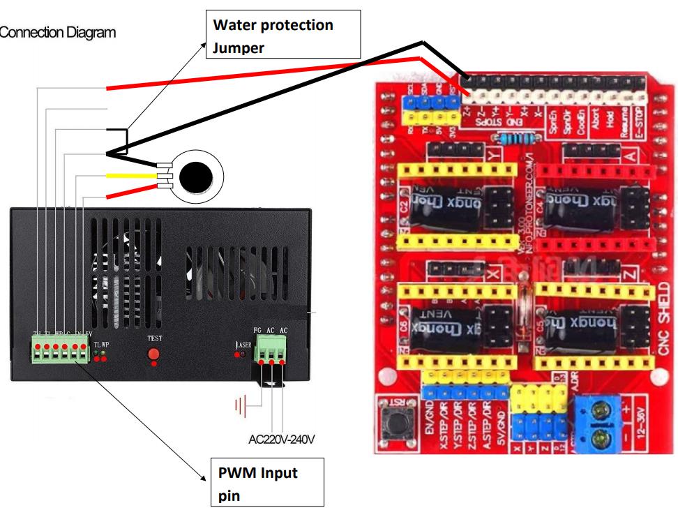
hi , yes the arduino is my controller , and the framware is grbl 1.1 , comunication between software and machine is not with sd or usb , its cable , the wiring in laser power side to arduino cnc sheild is this : IN → endstop Z+ , GND → GND , WP → GND , TL ->GND
so when is start my machine , because of arduino pins get fluctuate , laser start firing , and i need to solve this problem
You might be able to add a pull-up resistor to the -Enable signal to the laser’s HV power supply. However, if the Arduino power supply starts up slower than the HV supply, the laser will still fire.
A better choice would be a manual Laser Enable switch controlling the HV power supply’s AC input. This is common on CO₂ lasers, although it does require you to turn it off when the laser is not in use.
I would think something in the code must doing this… if you boot a 328p (Arduino) all outputs go into a tri-state mode. The lps will not fire if the line is open, it has to be electrically pulled to one state.
The Arduino, itself, on boot, comes up in tri-state mode, so I can’t understand what’s happening… It’s changing states via it’s software to fire your laser…
Have you looked at a different for the connection from the Arduino to the lps?
Maybe pwm to the TH input?
They wire these up a bit differently from the dsp type controllers where the pwm is on continuously, to the IN. The L (TL) line goes low when you want the machine to fire… requiring two control inputs…
Good luck
![]()
how can i do this ? for better explanation my lps has 5 pin as input/output beside the AC input , the pins are : IN ( as pwm input for laser power change during process) , gnd , TL( in catalogue said ‘trigger low’) and i think when low signal get to this pin( under 3.3 or something like that not matter ) , and WP ( as water protection , when this pin make short with gnd laser allow to fire ) , TH ( opposite of tl , due to catalogue means 'trigger high" when vcc voltage above 3.3 get to this pin lps allow to fire laser ) , and regulated 5v output for fir laser with potentiometer.
so due to my wiring that connect TL of lps to gnd , and my WP to gnd , the laser allow to fire when PWM signal in IN pin get , i think when i boot or turn on the arduino and lps at same time for period of time my pwm pin fluctuate or maybe in ‘input’ mode that has not exact input , so it fire the laser in this period , i must notice that i am novice , so can yo guy explain due to my components and material for better understanding? thank alot
The initial reset starts after the microcontroller’s power supply rises above the minimum level required to run the chip. Until then, the chip hasn’t gone through its Power-On Reset sequence and the outputs have no defined state. However, because the power supply is low, the microcontroller outputs will stay below the level required to keep the HV supply turned off.
The Arduino board’s linear power regulator (or the regulator on whatever PCB feeds the microcontroller) takes a while to haul itself to its feet and, because it’s downstream of whatever power supply turns AC into (maybe) 12 V, there’s enough delay in there to keep the -Enable line low.
If the HV supply’s AC input is turned on while all this thrashing around is happening, the laser will fire.
The basic lps has P (WP) which is water protect, L (TL) for a low laser enable and an H (TH) for high laser enable along with the IN terminal for power control…
If I recall these Arduino usually have the pwm wired to L or H.
IN controlled through a manual pot for dc input to control power.
Unless you built this from scratch, these controllers are all over the place working fine… So it’s a wiring or configuration problem.
You have everything on the lps hardwired to lase…
Can you clarify how yours is wired?
![]()
No shame in that: nobody is born knowing all this stuff!
The least complex way to ensure the laser does not fire is to turn off the AC input to the HV power supply with a manual switch.
I added a pointer and labels to the key-lock switch on my CO₂ laser:

That switch failed and I replaced it, but the idea still makes sense.
i think i do the same cause dont find the solution in wiring or add resistor , so i think safest way is to add manual switch and sequentialy turn the laser on after board boot up
thanks
I think you do not have it installed properly… you advised
As I stated, you are the only one with this problem and your hardware … indicates to me you have a wiring error…
However, if you wish to add some kind of interrupt switch… that’s up to you.
Good luck
![]()
thank you , let me explain my wiring , i connect Z+ pin ( in cnc shield arduino is 0-5v pwm ) to IN-lps
WP and lps-GND to thermostat relay , TL to GND , all wiring are sheild and all gnd has connect to each other , i detach other wires such as motors and microswitch to exclusively solve this , the arduino power supply wich is 12V for main board and 24V for cnc shield( motors) are siwtch power that has AC input like lps , so all ac inputs are at same source with some people protection at the start of line for safety , so thats it , when the power of machine get on , all
turn on at same time and as i explained , i get the pin issue .
This is not the standard way of wiring these, that I’ve seen … did you follow a specific procedure or article to determine this wiring?
Usually the IN terminal is connect to the sweeper of a pot to deliver 0 to 5V to the IN terminal for a manual maximum setting.
The pwm is usually wired to H (TH) or L (TL).
These are all standard ttl type inputs.
![]()
TL and TH isnt for enable the lps? so if i connect the arduino pwm to th how should it fire laser beam? because th enable the board , IN fire the laser beam ( i do this and say that based on catalogue and experiment test) , am i right?
The IN input determines the power level or current flow through the system.
The L or H inputs allow the machine to lase at the set IN power level.
Maybe this will clarify the connections, I hope you can read them… I’ve posted the link, but this looks correct to me.
Does this help?
![]()
IN connect to pwm , my wiring is same to this
Don’t think so… I read it differently …
It show Z+ (pwm) connected to the H input, not IN
It’s no wonder you’re having issues … hang in there … ![]()
![]()
thanks but it seem this diagram is for change he laser power with potentiometer so IN connect to output of potentiometer , and as turning it the laser power increase or decrease , so i cant understand why the TH pin connect to PWM of the board( Z+ in cnc shield is PWM , means that in gcode S0=0V and S255=5V , and it change linear ) i wonder why it do this and i doubt if it change the power in software , the power in this scenario seems to be Constance set by user, if i am wrong correct me cause i get confuse now ![]()
By the input names and descriptions on the lps, it’s not intuitively obvious how the low end controllers connect to the standard lps. I can understand your confusion if you’re just reading the documentation.
On a dsp, the pwm (IN) is generated continuously while the layer runs and it has a separate laser enable (L or H) when it needs it to lase.
The Arduino only has a pwm signal, not a laser enable signal. So the pwm that the dsp uses to feed the IN terminal is replaced by an analog voltage from a pot or variable power supply. Then the Arduino only has to enable and disable the laser.
From the diagram, I’d say this is your problem …
You will burn up a tube, with the way you have all the safeties over ridden.
I’m careful and pretty consistent and it’s stopped me from it not being powered up or something like a kinked hose…
You do have a coolant system?
You need to ensure that system is protected from interruption of the coolant flow.
![]()
thank you , yes i totally get what you saying , and as i mention the power of laser set by user with analog potentiometer and arduino just trigger or enable laser when it need , so this isn’t really help for a co2 laser machine to set the power constant by user , because during the process the nozzle didn’t have constant motion , it accelerate and decelerate , so the laser should adjust the power in process for best result , yes i have safeties like people protection fuse for leakage issue( lps has no joke high voltage and current leakage can kill instant ) , water pump and thermo-controller that if temperature get high the laser beam turn off or for better understanding an on/off control system not for example pid , and for my setup i use aqua pomp and tank of cool water ( radiator system not chiller for cost efficiency) ,so i think the best solution is to turn sequential due to your opinion the only way is the analog control , so fair and reasonable to make sequential tuning-on protocol for laser machine , that force user to do it , and yes as you said this issue can break the laser tube due to uncontrolled situation of laser in this period of boot-up , maybe later i switch to DSP controller for better performance , and there i hope i can learn from you a lot , thank for your advice and explanation