Reversing out of a Power Scale Test Setting

Many months ago I ran a power scale array test for cutting mounted photos on photo mount board. For my test I used minimum of 10% and maximum of 75% settings. I used 10% as minimum, because at the time it was my understanding that my laser wouldn’t fire below 10%, and I thought that might ruin the results of the power scale test. The best setting for cutting was at 45% indicated on the power scale (10/75 min/max).

Now, months later I’m ready to cut and am curious about settings in my “real” project. Obviously, I could set these layers to a min/max of 10%/75% and set the power scale to 45% and this would be exactly as tested in my power scale test.

However, that seems like I am having to set more values than I would normally. Given the math specified in previous power scale threads, the 45% setting at 10%/75% would equate to 39.3%. So, the question is whether or not that really holds true? Can I simply set my current project layer to 39.3% (40%?) without any power scale adjustments, and assume I’ll get the same cut I got on my power scale test?

Thanks in advance,
Ray
I’d invite others to pitch in but yes, I believe your math and how you’ve interpreted is correct. So 39.3% set directly should be equivalent to your test results at 45%. The only variable is that if you did this months ago that other changes in your setup might have changed or drifted.

Thanks. I did happen a try a cut at 40%, but unfortunately it didn’t even come close to cutting through. In fairness I masked the image with transfer tape, which I had not done previously, so that could obviously could have affected things.

It’s been a couple of weeks since I used the laser, so anything could have changed, although my last projects cut as expected.

Oh well no harm done. A second pass went through just fine.

Ray

No, certainly not. I keep a well documented material cut library and for the most part, pulling up previous settings works fine.

Were any of those factors in play? Very likely.

But to address my initial question regarding converting a power scaled output to non-scaled output, it would seem the best way to verify that would be run back to back jobs on the same material using both techniques and comparing cuts, thus hopefully eliminating those factors you mentioned.

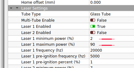
You might want to check to see how your controller is configured for laser power.

Screenshot from 2021-12-07 13-54-17

If I set my Max to 100% I will get 90%, since that’s the limit set within the controller. If I ask for 90% I’ll get 90% of 90 or 81%… 50% will be 45%…

:smiley_cat:

Thanks, I will take a look at that. All, of this to say, however, is that I am questioning the effectiveness of using the power scale function, when doing burn test patches.

When creating a burn test patch, you might easily have 100 or more patches to be tested, and given the limitation on number of layers in LB, the solution is to use the power scale function within layer objects.

However, if you cannot easily translate that power scale value back to a simple power setting (without applying a power scale offset), then I wonder if it renders the power scale function less useful?

I will admit in this case that my power scale test was made months back, and my test didn’t include masking over the mounted image (this was a test for cutting a jigsaw puzzle, photo mounted on mount board), while my final project did include that extra layer of masking. As mentioned, there might have been other factors, such as temp, humidity etc, that were different now vs then.

My question was meant to be a general purpose, i.e. “using the math of the power scale, can a power scale value be converted back to a standard power value”. The answer at this point seems to be “I don’t know for sure, it seems there could be other factors in play.”

Bottom line, on this particular project, after the one cut pass nothing had cut through at all, and running a second pass quickly solved the problem. However, I will say I am not confident I can take my previously cut power scale tests from other materials, and believe I can use them to determine proper settings for an effective cut. What I could do, certainly, is use the “expected” value, and do a small set of test patches, not using the power scale function, but using regular power values around the intended target area.

Thanks everyone for the input. Much appreciated.
Ray

I think I’d characterize it differently. I think the answer is that yes, the power factor from a numeric perspective can be reverse derived. However, the applicability of the results of the initial test depend on a number of factors that may change in the time after the initial test.

I’d take this as a reason to either retest often as conditions/variables change. Or have a much more thorough set of variables accounted for in the initial tests. This narrows the applicability of those results to the specific variables accounted for but could allow for high repeatability in results.

Not sure if I’m following you, have you ever looked at this generator and see if it’s applicable to your needs.

I’ve used it a number of times…

https://www.o2creative.co.nz/laser/lightburn_basic_generator.php

Good luck…

:smiley_cat:

@jkwilborn sorry this is confusing. Yes, this is exactly what I used. Several months back, knowing I would at some point want to do a mounted photo as a jigsaw puzzle, I did a power-scale test, exactly like in the link you posted. Major difference in my test was that my minimum power setting was 10% and my max power was 75%. I did several rows of circle objects, changing the power scale from 10% to to 100% along each row, where the row was a specific speed setting.

The best cut from the test indicated that using that power scale, the object at 45% power-scale was the best option at 20mm/s.

Now, several months later, I wanted to cut a jigsaw puzzle. Working the math backwards from the previous power scale test (layer min of 10%, max of 75% at indicated 45% power scale), this worked out to a 39.25% equivalent power. So, I set my project to burn at 40% power (no power scale applied) at 20mm/s. And, end result was that it didn’t even begin to cut through the material.

Was the failure due to miscalculation on my part? Differences not accounted for (material, temp, humidity etc) as another suggested?

One way to probably be more certain is to run another power-scale test, immediately followed by calculating the effective power from the power scale, and cutting immediately with same material, but cutting with calculated (unscaled) power, and comparing the cuts. That at least would rule out those other factors like material, temp etc.

At this point it really is just a curiosity. According to other power-scale threads, and to calculations specified by Oz, I would have expected that a cut set at 20mm/s @ 40% power to have been effectively the same as my test row, which was 20mm/s 10% min and 75% max layer power setting, with a 45% power scale setting.

Thanks.

1 Like

That test, as far as I know that link was for engraving information.

You are basing the ‘cut’ parameters on that, just to be clear?

I don’t know how relative it is to a ‘cut’ of the material.

Maybe I’m just confused, wouldn’t be the first time…

Why did you ‘make’ adjustments to the known cut value?

Probably academic anyway at this point…

:smiley_cat:

Hey Jack,

The link provide above goes directly to a cut test. There is a link on that page to an engrave test, but the only difference is that the layer parameters are set to fill, rather than line.

As you indicated it is certainly academic at this point, but I will admit to say I am curious as to what caused the cut failure.

Why did I make adjustments? Well, in normal operation of my laser, you set three layer properties, whether cutting or engraving. These properties are speed, min and max power.

When making a power-scale test project, there is a 4th property that has to be set, and that is the per-object power scale fraction. All objects on a particular layer would have the same speed, minimum and maximum power settings. However, with a power-scale value less than 100% (the default) applied, the actual output power is supposed to be scaled between the layer minimum setting (at PS == 0%) and the maximum setting (at PS == 100%). So a power scale value of 50% should in theory be right in the middle between the layer minimum and maximum power setting values.

Back to your question, why would I make adjustments? In normal operation I don’t want to have to set a power scale fraction, I only to just set speed, min and max settings. So, the goal of this whole thread was to determine if the correct power settings could be backwards calculated from a power scale test.

The other reason, perhaps less obvious, is that I store all of my cut settings in a LightBurn Material Library. Those cut settings include everything that is in the cut dialog box, HOWEVER, there is no setting in the material library for a power-scale offset. Using the material library to set your layer parameters for a particular material does not set (or change) the power scale fraction on any objects in that layer.

Anyway, I hope that clears up why I would want to back out the non-power-scaled power value from a power-scale test. As mentioned, my project mentioned in this thread is done and finished, so at this point it’s a matter of curiosity as to why it failed for me.

This is a limitation of the Ruida hardware itself - we’re just working with what we’ve been given. :slight_smile:

Your math is correct - 45% of 10/75 will be 39.3% power output. You haven’t mentioned speed anywhere in this post though. Were the speeds the same? And if so, what speeds were you running?

Hi Oz, thank you for the reply.

My initial power scale test had three layers, running 10, 20 and 30 mm/s. Min/Max settings were identical on all three layers, i.e. 10%/75%, and power scale settings ran from 10% to 75%.

The perceived best cut was 20 mm/s with a 45% power scale offset.

My final project cut I tried at 20 mm/s with min and max power both set to 40% (I rounded up from 39.3). It did not even begin to cut through the bottom of the material at all.

Thanks,
Ray

PS: Thanks for the clarification on the number of layer restriction of the Ruida controller.

I believe it’ll be the same output from the controller, but I haven’t hooked it up to a scope to verify this.

This topic was automatically closed 30 days after the last reply. New replies are no longer allowed.