I wasn’t aware that folks paid attention to profiles. My point was to add that to original question so everyone better understands the post.
Now that you mentioned my profile I think the best thing is to clear it completely. I’m normally providing tips and guidance on this site. Considering that they are not hiring me and in the end they are not obligated to follow my advice, what purpose does it serve?
Being an engineer and working with engineers all my career I’ve had many disagreements. That’s natural and healthy. In the end no one is really right or wrong. We are just offering safe ideas for folks with less experience to consider. Just have some fun
well, i don’t see a reason why not. as mentioned in my first post these tables i’m retrofitting don’t have a Z-axis, their actual tool is a binary on/off. ‘power’-control aside - this seems to me very similar to what a laser-engraver does, it leaves a trace in the workpiece - or not. on - off. if the ‘binary’ tool is a focused ray of light, a pen, crayon or even a spray can shouldn’t really matter for the software sending the job.
i had briefly looked at vcarve before, but it seemed to be way more a tool for the kind of CNC-router/milling machines with various tools to attach and substracting substantial amounts of the workpiece’s material. the classic ‘engraving’ we’re trying to replicate was way more of an ‘etching’, displacing material.
besides, Lightburn seems very much ‘design’-centric, in terms of doing plain 2D graphics with it and prepare them for this kind of line-based replication on hardware.
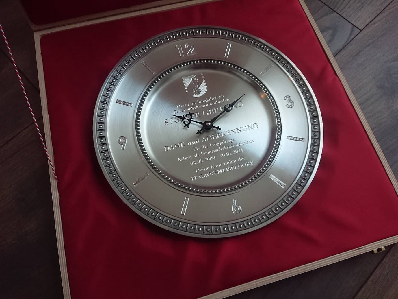
yeah, pretty things can be done and have been done historically when it’s still been a handicraft around here. my former client (i took this over from, now that he retired) started trying to bring this over to the ‘computer assisted age’ in the late 90ies already. knowing the system, i can tell that back then it’s obviously been quite a feat for a company like Newing Hall to make such machines affordable for a broader market.
but with all the advancements of the last decades, the knowledge and (open) standards which have evolved, i know that a lot of things can surely be done better, definitly more efficient.
so for sure i’ll soon try to get this valve clicking with a mosfet from the ruida…
I don’t see this fundamentally different from the other user on this forum using LightBurn to control a plasma CNC. I think you’re good.
And as you’ve stated the problem space is actually easier since you’re dealing with a binary on off state with the drag tool.
Also @dean448 to clarify this is not a drag knife like what is used in a vinyl cutting machine. That would require a different tool path that LightBurn is actually not currently equipped to handle.
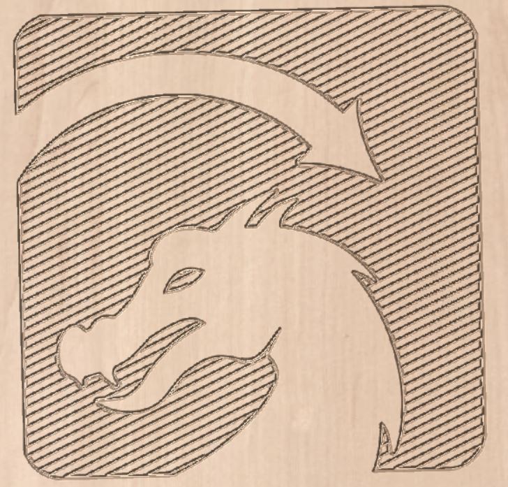
The reason I don’t think it’s a match is because when Lightburn engraved it scans in the X direction only. When you look at a V carving it follows the contours. It does that automatically. You specify the inside and outside of curved surfaces and it figures that out. With Lightburn you would have to create that filled area with vector shapes. Since it can only fill something in by horizontal scanning. Only horizontal lines would look terrible.
you mean with VCarve one could define/create hatch fills? gotta confess i didn’t check if Lightburn can, our graphics including fills had been done in corel draw till now - i myself am doing it with illustrator now. hatch fills are a pain there either, but one gets used to it.
which is one of the horribly weak points of the original, ancient system: the software which talks to the controller can only import .plt from corel draw (at least i wasn’t able to get a compatible file from any other source yet) and does so by converting it to pixels which then are traced back to ‘their’ vector-format. i’m really looking forward to finally seeing really smooth curves from this machines…
The closest thing to this that’s currently built-in would be the offset fill cut type. You’d have limited control of how it does this though.
Would it not be better to hand draw all fill as vector lines so you’d have exact control of this? Are there difference sized drag tools that would need to be accommodated for?
Is this some sort of plotter format? I know some plotter software can account for different pen sizes in their fill operations.
yes, seen that and will definitly use this for type - which often will be done in Lightburn itself and benefit of such ‘concentric’ fills. the original software had dedicated fonts included designed as such.
everything else - as you say - will definitly be done in a better suited program, as is now. size of the tool is fixed, so no need to accomodate for that.
what theoretically would be a nice-to-have is a kind of ‘parametric hatch fill’ - adopting to the actual output size of a graphic as the gaps between lines scale with the object, so there’s too little fill when going big. but realistically that’s a non-issue and one just can do the fill again should it be needed.
yes, it actually seems to be some kind of dialect of HPGL, but i never got it working with anything named HPGL from other programs. but didn’t do that much of research either, as the import process of the program is rather useless anyways.
Maybe I’m misunderstanding but instead of the gaps between lines scaling wouldn’t you just need more lines to fill-in the expanded area? If so would the only parameter for this be that the distance between fill lines stay static as the area of the fill area grows. Meaning that more lines would need to be added to accommodate the area? Does this mean that area would need to be evenly divisible by line width?
granted, i haven’t put much thought or trials into this yet, just thinking to myself whenever i do such graphics: hey, this can’t work if i ever need to use this at a considerably different size.
but yes, for the hatch fills the gaps would need to stay the same or at least not grow at the same rate as the object is scaled.
though with a smoother workflow (which i’ll have with Lightburn) this isn’t as much of an issue anymore anyways.
I think you could approximate the correct line distance by using the line interval feature in LightBurn. This will also scale infinitely with area so quite convenient. Also can use the ability to change scan angle to provide a different look.
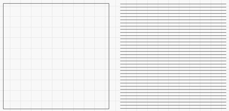
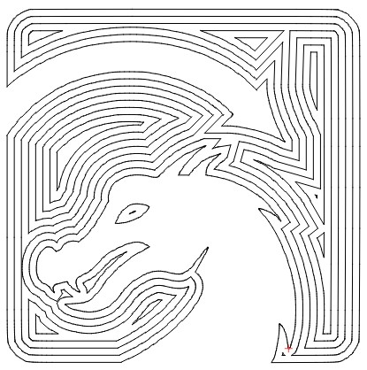
Check out these samples.
Left is 100x100mm regular rectangle. Right is sample created with “Convert to cut (debut)” with a line interval set to 3 mm (just guessing at bit width). This shows how it will be interpreted as lines.
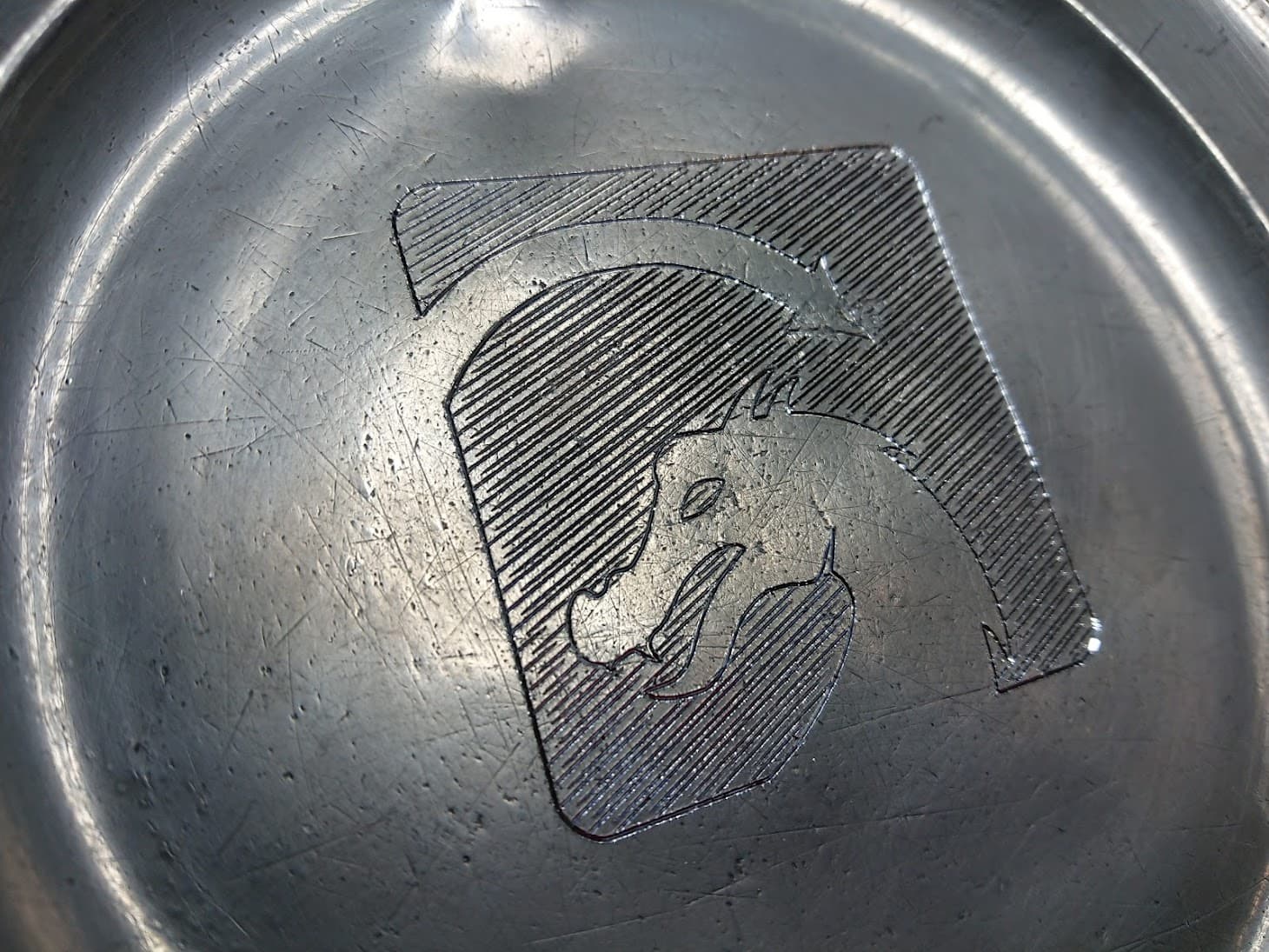
still some things to tune - but generally things are looking good…
mosfet seems to be switching too late, so i’ll probably indeed will need an ‘L’ (logic level voltage) and the diagonal lines being differently spaced must be some step calibration issue (horizontal and vertical ones by themselves are fine).
also need to identify what all these timing/speed/acceleration-settings of the ruida do
Could you remedy this in software with Offset Scanning Adjustment in Device Settings?
Do your horizontal and vertical dimensions look correct to design? If so, then probably not a step calibration but seems odd. How did this look in Preview?
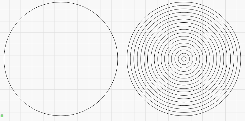
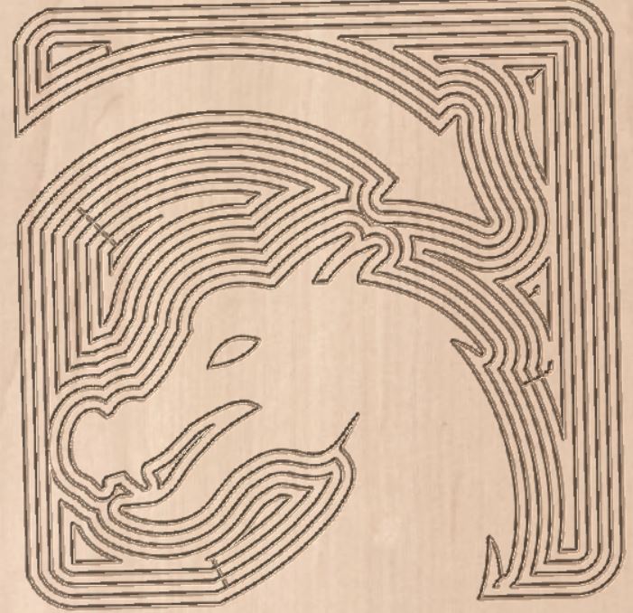
Not sure what you mean. The tan images are from a different system and a simulation.
My point a while ago is that LB can’t fill with curved lines so this is an example of that.
Oh… gotcha. I thought you were using simulation more figuratively. As in a dry-run.
Offset fill would give you an approximation of this with limited flexibility. Will try to think of a way to do this more flexibly. Possibly doing this semi-manually using insets.
Yea I’m just throwing it out there. No idea if this look is closer to what Markusa is looking for. After all none of us will ever have a machine like that. Or could get a better result if done manually.