Reviving old engravers with Ruida&Lightburn

quick intro:
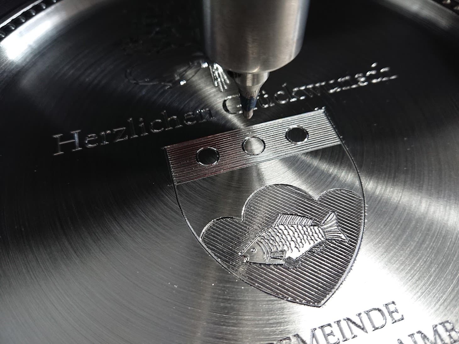
I took over 3 old ('90ish) Newing Hall engravers which i had kept running for a client over the last 20 years yet - so i knew that the original setup of software and controller would have to be replaced for any serious work and modern workflow to be done with it.

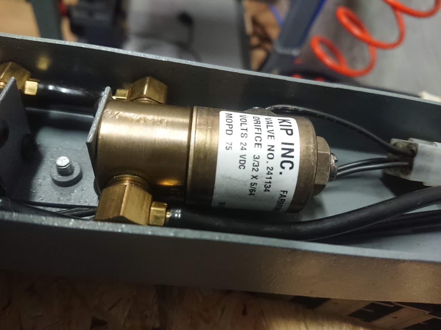
the machines are simple x/y-tables with a solenoid valve to pneumatically drive a tool into the workpiece - so simple on/off of the (not-)laser.

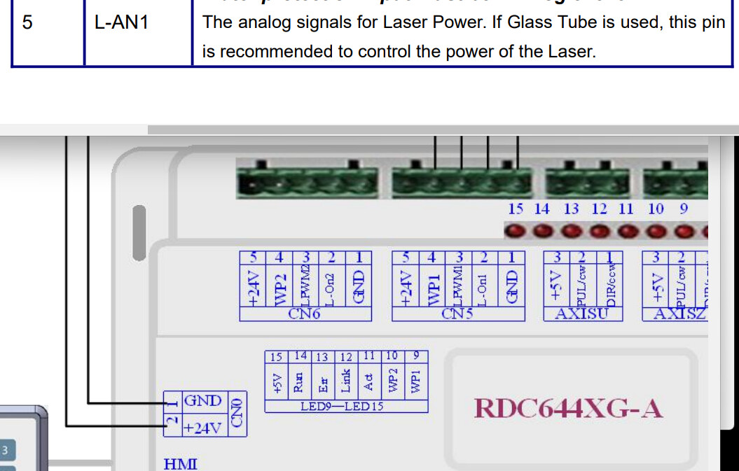
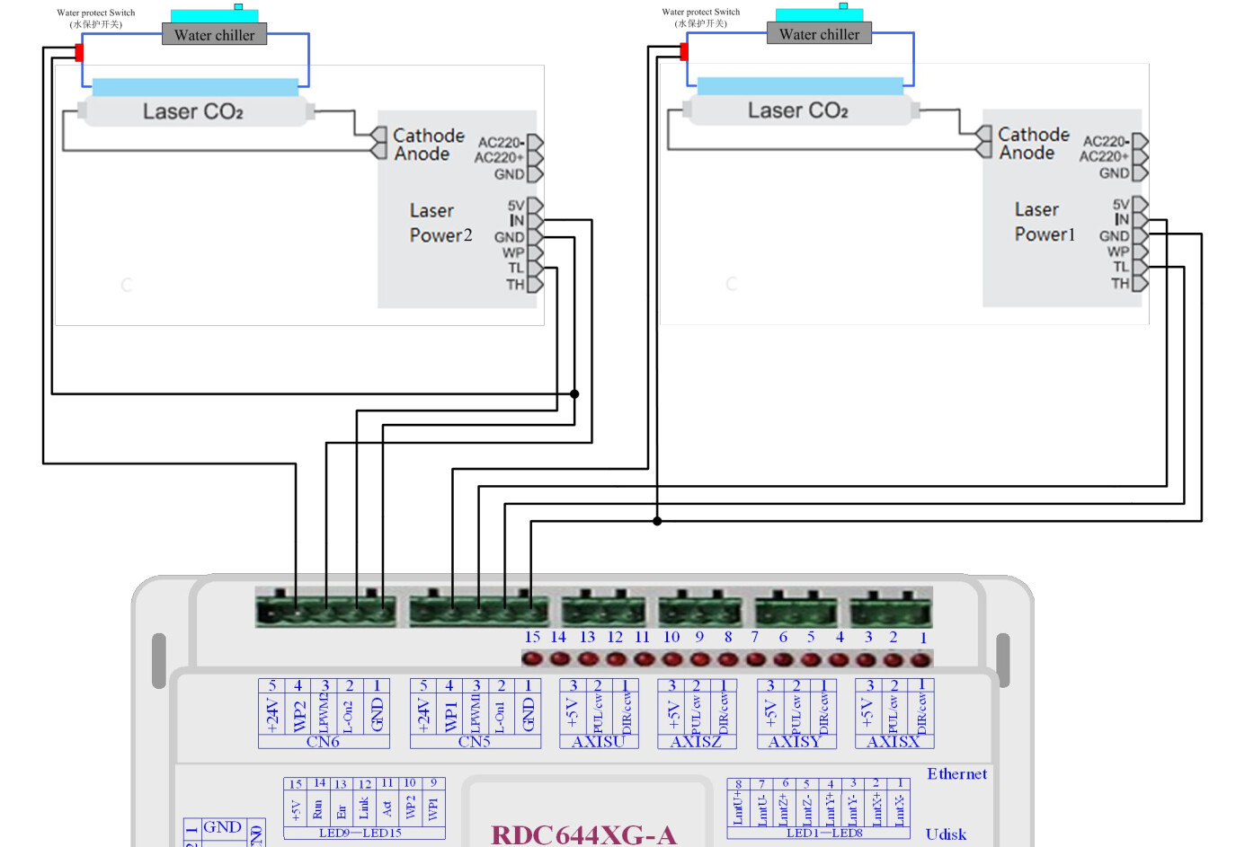
i’ve been tinkering with several approaches to retrofit these with some new controller (mach3, smoothieboard, linuxcnc) - but wasn’t quite fond of any of these till now - and that’s where i happened to discover Lightburn (right after buying a cheap Neje-Laser). Realizing it also supports controllers of ‘bigger’ machines and finding these being available separately and even include things like a control panel and could be controlled via network i ordered a Ruida 6445.

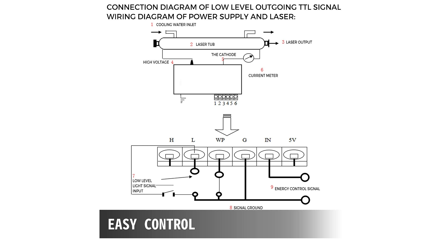
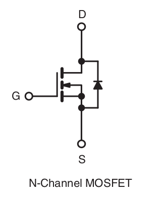
It was easy enough to get things moving, but now i’m at the point at which i’d need to control my (not-)laser. obviously it’s not PWM and i know of the danger of solenoids shooting voltage back to the controller - so i hope that someone round here can give my guiding hints on how to best approach this.

tia,
markus.

1 Like

of course my main issue here is lack of knowledge about lasers.

after studying a bit more of documentation - which is rather slim on Ruida’s side and understandably not that hardware centric on Lightburn’s - i stand with some questions:

  • if setting the laser type for CN5/6 in ‘factory parameters’ to ‘glass tube’ there’s said to be an analogue signal on pin5. since that’s marked +24V i assume it’s voltage ranges from 0 to 24 volts relative to the laser power requested by g-code. right?

  • assuming i’m setting the laser to fixed 100% in Lightburn this should give either 0 or 24V, right?

  • i guess directly connecting a solenoid-valve to this output isn’t a good idea and/or a diode is on order to avoid flybacks of the inductive load?

  • does anyone happen to know what loads may be drawn from this 24V pins?

  • is there any other way to get a clean(er) on/off signal for a laser’s 0-100% power? i’d sure be able to hack some circuit with a mosfet even it was a lower voltage signal only.

thanks again for any input.

I think all the logic outputs on the CN5 / 6 connectors are 5v output, and they’re very low current - you’d need to connect through something like an op-amp, transistor, or solid-state relay to drive anything with a significant current draw.

The analog signals for Laser Power. If Glass Tube is used, this pin
is recommended to control the power of the Laser.

so says the manual :tipping_hand_man: (mind the +24V on the pic)

but yes, will have to throw the multimeter at it tomorrow anyways.

They are ttl, both LPWM2 and L-ON2. WP2 is the water protection input and is active low.

:smiley_cat:

i referred to pin5 or “L-ANx” - which in the one pic of the manual is labeled +24V and is said to put out an ‘analog signal’. but it’s 5V indeed - haven’t bothered hooking up an osciloscope yet.

in Lightburn’s “Vendor settings” there’s a low/high for Laser Output Signal - but i couldn’t figure out yet what it’s actually doing.

so - on to the real basic questions: what does pin2 - labeled “L-On” - really do?
i assumed it was some kind of ‘arming switch’ for the laser which is turned on at the start of a job and the actual firing of the laser is done by the pwm-signal. but it seems that there the voltage drops while the machine is travelling while not cutting/engraving. is this where i should get my on/off signal for my solenoid?

I’m not certain but between this and what @jkwilborn indicated this could be a simulated analog signal with PWM running 24V with a duty cycle to get to a 5V TTL. On a scope this would probably look like 24V with a 20% duty ratio. If I’m thinking of this correctly.

This is super interesting and I want to do a similar thing with a plasma cutter / DIY plasma table.

If the original control system of the engraver is 24VDC and the solenoid deploys at 24VDC there are some excellent Back-EMF trapping strategies that involve a diode (or two) to short the spike to ground. The most clever trick i saw involved a zener diode to additionally clamp Back-EMF at its regulating voltage to shorten the transient time of the spike.

I would be thinking along the lines of a solid state relay to trigger the engrave head with a PWM strategy as the old controller may have had a capacitive tuned circuit to introduce the motion gently. In my experience 24V matches transport truck (Lorry) electrics and solid state relays may be easy to acquire from repair shops or industrial suppliers. Vehicle components are often more rugged than hobby / light industrial parts - I’d be looking there first.

1 Like

The L-ONx is for the lps (laser power supply) ‘enable’. Mine goes to the TL input of the lps. It has to be ‘low’ (hence T’L’, the other input is inverted as T’H’) to enable the PWM control.

The LPWMx outputs are 0 to 5v and drives the lps via the ‘IN’ control. With TL low the lps will turn on with a positive state (5V) on the IN pin.

My Ruida does not have a L-ANx connection.

I think this clears it up for the Ruida. This is really from the 6442G series manual.

Here is one where the TH & TL are referenced as H & L.

Most of these outputs that ‘drive’ something are generally ttl, so be careful. I have looked at it with a scope and actually have a connection to the PWM specifically for the scope/trigger.

I doubt that any of the control pins operate at 24 volts. In that I mean that only the ‘solenoid’ related items need be 24v. The analog output of most controllers run from 0 to 10v, at least in the limited amount of cnc machines I’ve worked on or used. Maybe a better way to put it, is that if it has to interface to another part, such as the lps, it’s probably a ttl control line.

I use the IRFZ44 power mos-fet. The cost for 20 units is < $10 from Amazon. These and most power mos-fets today have ‘integral reverse p - n junction’ protection diodes. I have multiple solenoids on my Ruida and NO diodes… well, I have two now, for air assist. Replaced the others with ssr.

Screenshot from 2022-01-07 14-47-17

This describes how ‘tough’ they are…

That sure used to be the case. Most of these types of electronics are now solid state, generally the power mos-fet devices are more dependable than any mechanical device, low cost, can be driven directly from a micro controller and can switch large loads. What’s not to like… :crazy_face:

Keep your design following how the Ruida is designed for I/O and you’ll have little trouble. Keep it simple…

Good luck

:smiley_cat:

2 Likes

Jack’s post is correct down to the mosfet section where I’m lost about what that would do in this situation.

In the illustrations:
The only thing I don’t agree with is the laser PS WP pin is open and the water protection goes to the controller. You could try it that way but I would just connect water protection to WP on the PS, which is safer. Water stops which shuts the PS down but the machine will keep moving. This should almost never happen if your using a good chiller. It might depends on the PS, but mine wouldn’t operate without WP pin grounded at the PS. That pin also supports door interlocks etc all in series with water.

I think they are more interested in the controller setup and not worried about the wp being open. Most of these don’t show complete setup, just to illustrate the major points they are speaking about.

They don’t show any wires to the mains either…

My point about the mosfets are they can be driven right off the PWM output of the controller…

:smiley_cat:

ok. so that’s what ‘Laser Output Signal’ low/high in the Vendor settings does - defining if L-Onx goes high or low as different LPSs might have different requirements.

my noobish Laser-question still stands:
when is such Laserpowersupply acutally turned on or off? is it enabled while travelling ie the Laser not set to a power >0%?

thanks for all the input so far.

Not sure I understand the question…

The PWM signal controls when the laser fires. The L-ON signal is an ‘enable’ signal for the PWM control.

The only relation to speed is that done within the controller to adjust the pwm (min/max) for the head slowing and changing direction to maintain a constant damage to the material.

If you think about it just doing a line, it turns on and off via the PWM.

PWM is the illusion of power control for your laser. Generally speaking the laser is on or off there is no 50% lase, it is on or off. At the 50% power level you machine is in full power lase 50% of the time. The PWM and speed allow for the illusion of control of the power by distributing it over time. When it comes down to it, the only real control you have is speed. :crazy_face:

If you can get your head moving fast enough (and a low pwm frequency), you will see the pwm pulse marks and they are not contiguous.

:smiley_cat:

see, i’m even lacking the right words to talk ‘laser’ :hugs:

by ‘travelling’ i meant moving the head/tool/thingy-where-the-bright-dot-is-coming-out without the laser actually leaving a trace on the workpiece. for example moving between two separate objects to be cut. is the laserpowersupply ‘on’ while doing this or is just the power dialled down to zero?

Going back to your your original post… do you need to engrave photos? Or just cut out parts?
If just cutting, then you could hook a potentiometer to the IN pin and then find a way to turn it on and off. You could simply control TL pin using a relay driven from a cam attached to a small stepper plugged into the Z axis drive.
No need for a laser controller. Just use Mach3 and set cutter depth to 1mm or whatever and the cam rotates to a position that triggers to relay.
You can’t engrave photos without a controller.

no photos, no cutting. unless a diamond-drag-tool etching metal counts as cutting :man_shrugging:

also, no IN or TL pins, since there is no Laser to power put just such modest solenoid to trigger:

for sure it could be done easier or cheaper, but currently i’m quite fond of that Ruida-route in combination with Lightburn as it looks like quality and workflow fits quite well for what we do … and even things like the rotary setups and beltdriven(!) spindles we have for this seem to be easily implemented…
:hugs:

I guess I should have just asked for a more clear explaination. Sorry…

If the pwm is set to zero, it will remain low and the laser will not be firing. The mechanism that is implemented is unknown to me. Could be the L-ON1 or the pwm or?

That is a good question, next time I’m out in the shop with the scope I’ll have to look and see what it does. Does it disable the laser via L-ON1 or by a pwm of zero? Either way would work. I’m afraid someone @LightBurn would have to answer that question.

Sorry about the confusion…

:smiley_cat:

Dragknife? So you don’t have a laser but like Lightburn and a laser controller?

I don’t think Lightburn is set up to control a dragknife. A dragknife is like V carving which means Vcarve from Vectric. Post gcode to Mach 3 and whatever controller that you choose. I don’t think a laser controller would work for this application.

I jump on a number of threads at the same time and they get confusing. This topic sure felt that way. Didn’t we touch on Mosfets at one point or am I confused?
I wish folks would say what equipment they have, their problem or needs and what country including if they are translating from English.

To be fair that background was in the initial post, though that was many posts ago. @markusk knows the challenge and is attempting to repurpose LightBurn for this application since he’s fond of the software.

That is a beautiful engraving. I can see why you would like to use that equipment if possible.

Oz mentioned in one of his posts that he would like to support ‘knife’ cutting equipment, but had issues with the manufacturer. Since yours is unique it might not be as attractive as a completely commercially built unit, but the basics of operation should be very similar.

Maybe @LightBurn can drop in with an opinion. I think you could easily ‘drop’ it with the pwm just running it at 100% for the layer…

Good luck, thanks for the photos.

:smiley_cat: