Eleksmaker ManaSE board
LB 9.2.3
Using Y-axis as rotary axis
GRBL 1.1e
Rothman 32bit black/blue nano
I am trying to develop a follow along process for customer to be able to calibrate my chuck style rotary and as I am in the calibration process I find myself stuck.
I am able to fully and accurately calculate my steps per rotation. I can then follow this through and measure the circumference of my different objects and place/level/focus them and for all of them I can accurately burn a circle square or line.
However
Any bitmap/vector/svg/image, continues to come out larger, (even on the same x-axis/circumference)
The proportions are correct, it is just that the design is expanded outside of the size constraints I set in the software.
The way I understand is that the software uses an algorithm of angles to burn when using the rotary(?) I was thinking that this may be a bug that processes those moves by expanding outside of the set dimensions as opposed to keeping them within them(?)
It doesn’t know it’s really using the Y axes to drive a rotary.
In your case, with a chuck type, it does have to compute the circumference to rotate it properly. If that’s what you mean, yes.
There is no extra computation for the actual engraving. It doesn’t know or care the shape, it’s a 2d design that is plotted onto the Y axis just like it was flat.
Many people have problems with vector engraving. The object tends to move slightly usually from ‘slipping’ in the holder. I have it with my wheeled rotary and I have all my speeds set way low.
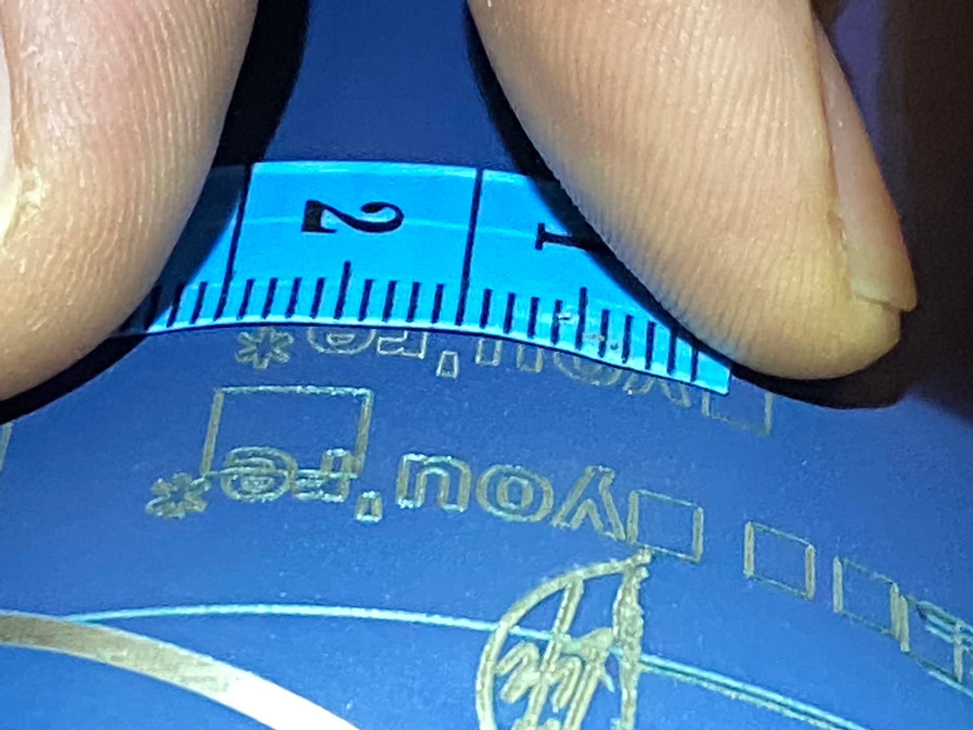
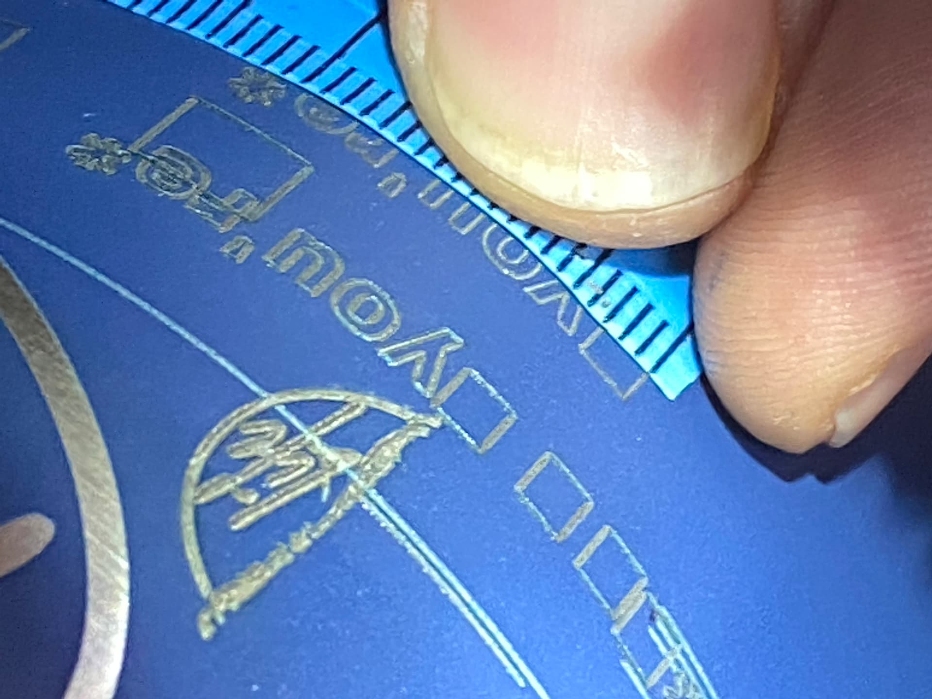
Yes, so sorry I forgot to include them originally, you can see the correct 3x3 as example and the 5x5 circles(even though tape is held crooked) and then an example of an svg “expanding” from 20x3.5 to 24x4+
Just so I’m following along let me reiterate my understanding. Correct me where I’m off.
You’re showing a square that was designed as 3x3 mm and measures 3x3 mm
You’re showing a circle that was designed as 5x5 mm and measures 5x5 mm
Based on the 2 points you would believe that engraving is working correctly.
However, when you engraved an SVG of size 20x3.5 mm design size it has come out as a measured 24x4 mm? Is this the “You’re*” you’re showing in the top screen shot?
Please confirm I’ve got this all correct.
Some followups assuming the above is correct.
Can you send a screenshot of the design in LightBurn?
The “You’re*” was burned as a line or this a filled outline?
Same question for your square and circle
Were the square, circle, and “You’re*” all burned in the same run?
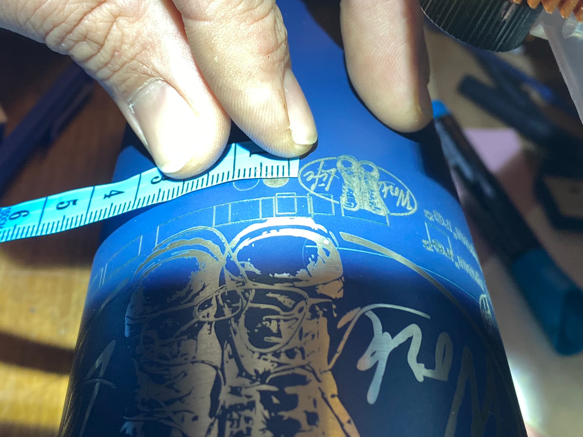
What are the actual dimensions of that container (bottle is it?)
So based on the a 3x3, 5x5 5x10 10x30 square/rectangular boxes and 5x5 circles and 30,50,100mm lines and one 100mm line with the circumference set to 100 and it went to tip, all these showed correct and accurate, the square/rectangular boxes were line and also on fill, the circles did one just line and one in fill, the you’re* I did just line (and that was an imported svg graphic not created in lightburn) the actual circumference of the tumbler at engraving of these pics (centerline to graphic) was 272mm
sure, the square I continually resized so i believe it only shows the one, if this carries any settings i have been changing them along with someone in messages step by step so not sure what it will show but can always revert to right where i was and re upload if that’s the case ROTARY WORK SPACE.lbrn2 (15.5 KB)
It seems that from working with Tim Rothman, he was able to determine that my linear calibration (setting my x/y to anything other than 200steps/per for my .9/16tooth gearing setup) was throwing off the scaling, I set to 200, recalibrated my steps per rotation) and now everything is cohesive and correct! Magic numbers ftw!
See that’s what got us confused about it, but sure enough after setting my $101,$102 to the standard 200(.9/16t) then I was able to recalibrate same results but also the graphics held their proportion, it’s truly got me scratching my head but at least now it is actually working exactly as it should when using the steps per and circumference values! Any thoughts on why this was a fix?
They were set at 201.7 and 199.3, so very close, only tenths of a point off when I did the calibration, I’ll definitely look through the write up about the steps per