I apologize if anyone is repeating themselves, but i couldn’t find anyone having this issue and it wasnt the steps per rotation.
I bough a monport 30w fiber laser and have used it for a year, exclusively using Lightburn.
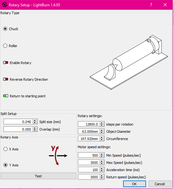
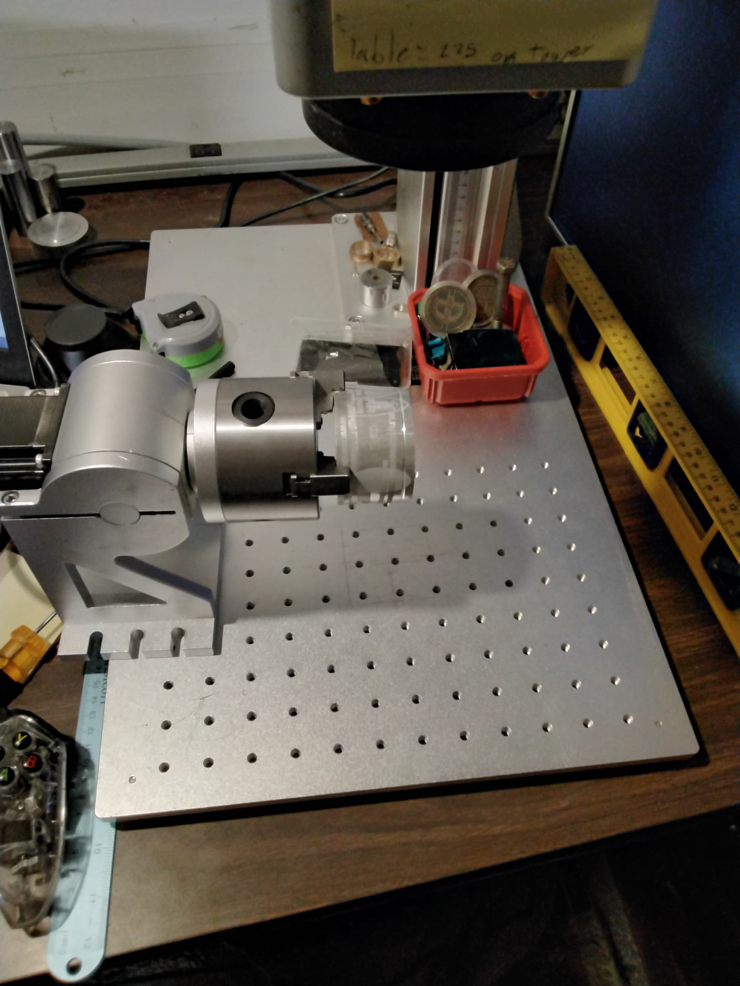
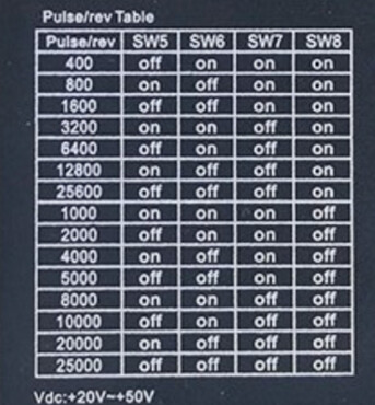
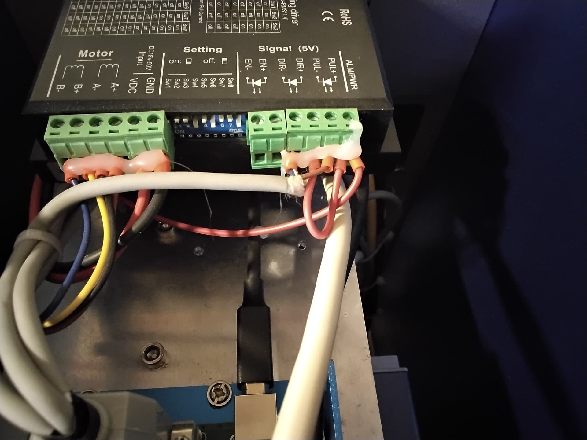
Now i bought a rotary chuck, wired up the plug according to the diagram. My dip switches tell me its 12800 steps per rev. When i set Lightburns rotary settings to 12800 the test button works perfectly. I set everything up according to the lasereverything guy on youtube.
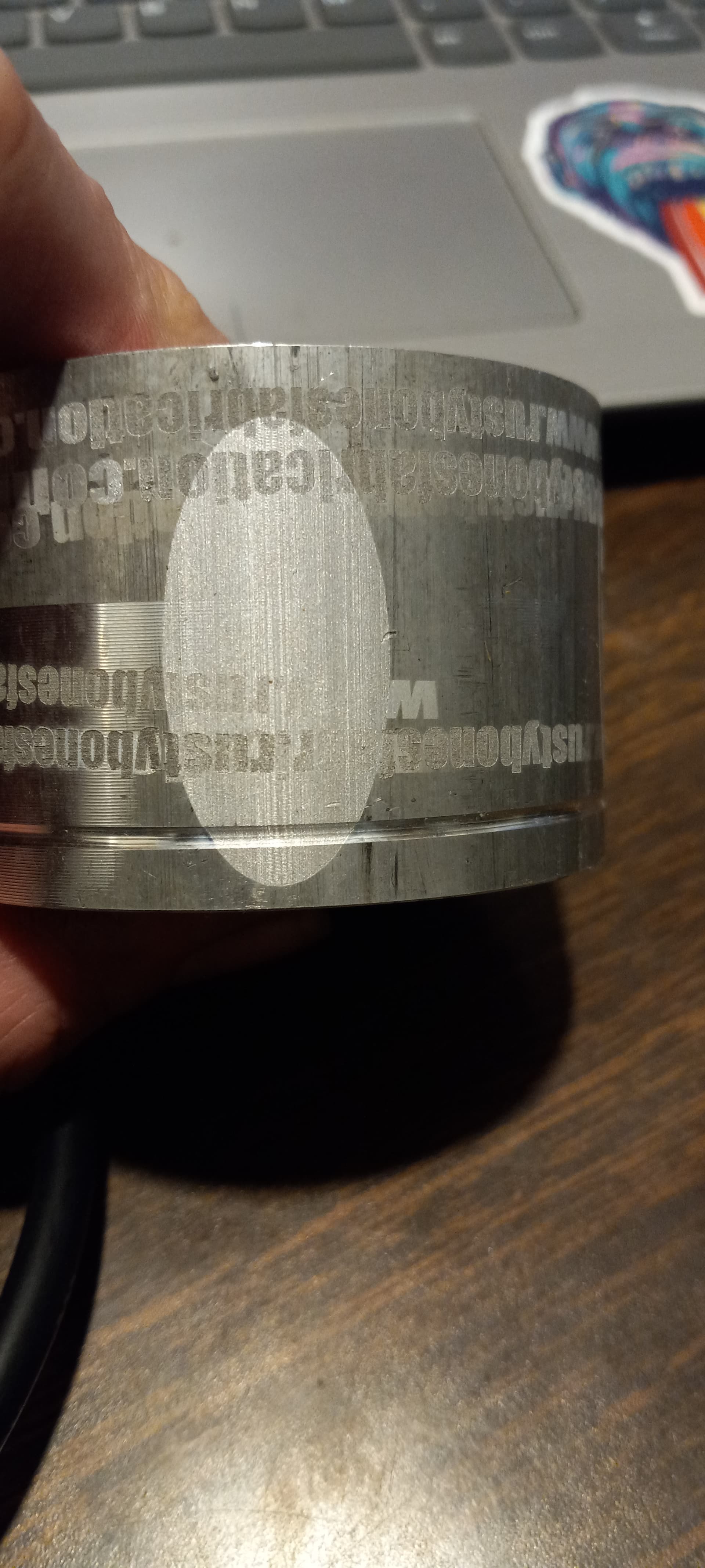
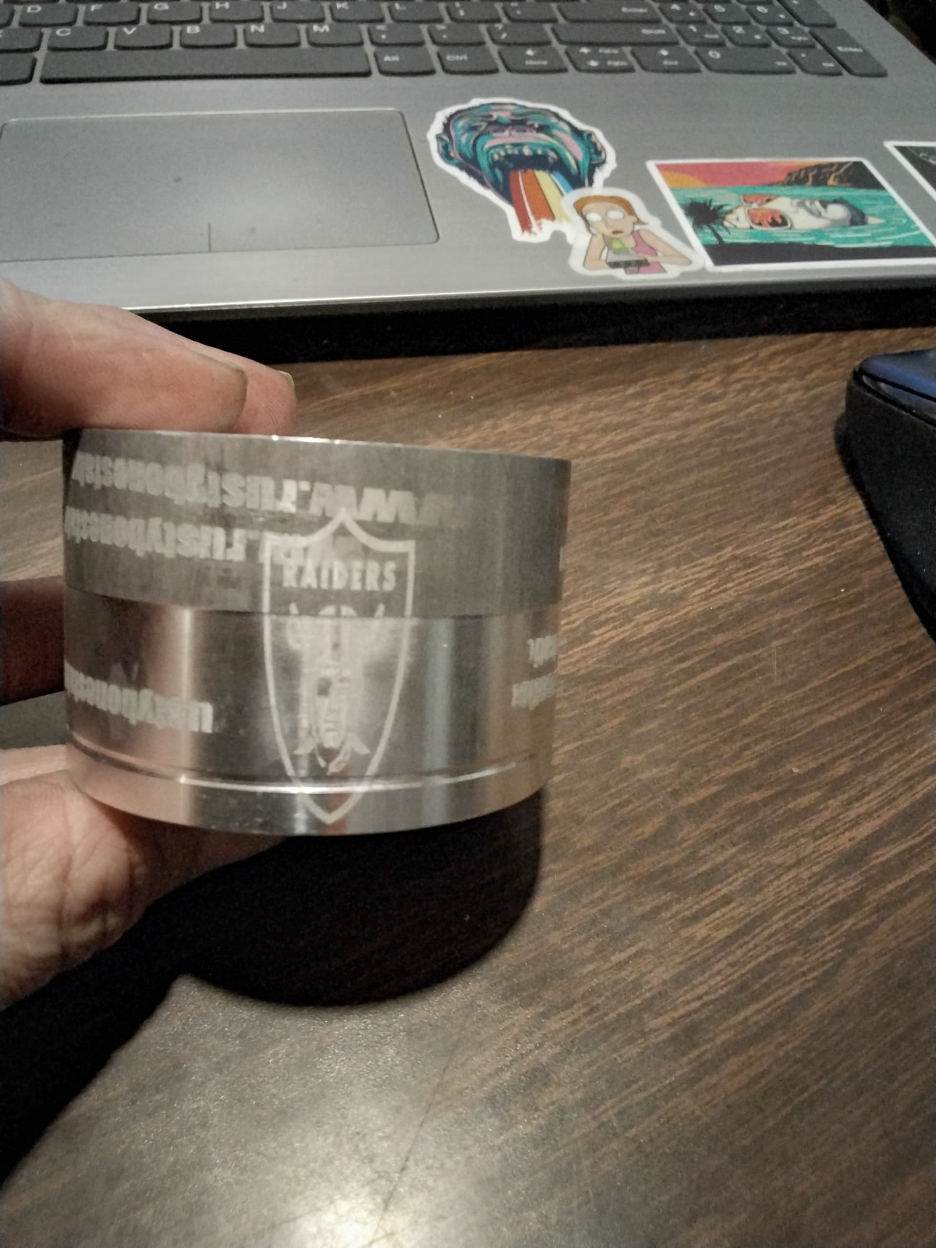
I evngrave and the image is smashed in one direction. The axis that wraps around the object. I feel like im just missing something obvious.
I dont know what my, or what a controller is and if you need that info. Never used ezcad, and im always on the current version of lightburn. And im also 100% correct on the diameter of my part as well.
It has the appearance of the diameter not being incorrect, it’s squished the right direction for this …
I’m trying to compare it to your chuck size, which I assume is a D80?
If the test button in Lightburn rotates it one complete turn and back, that would seem to verify all everything from the software through the hardware.
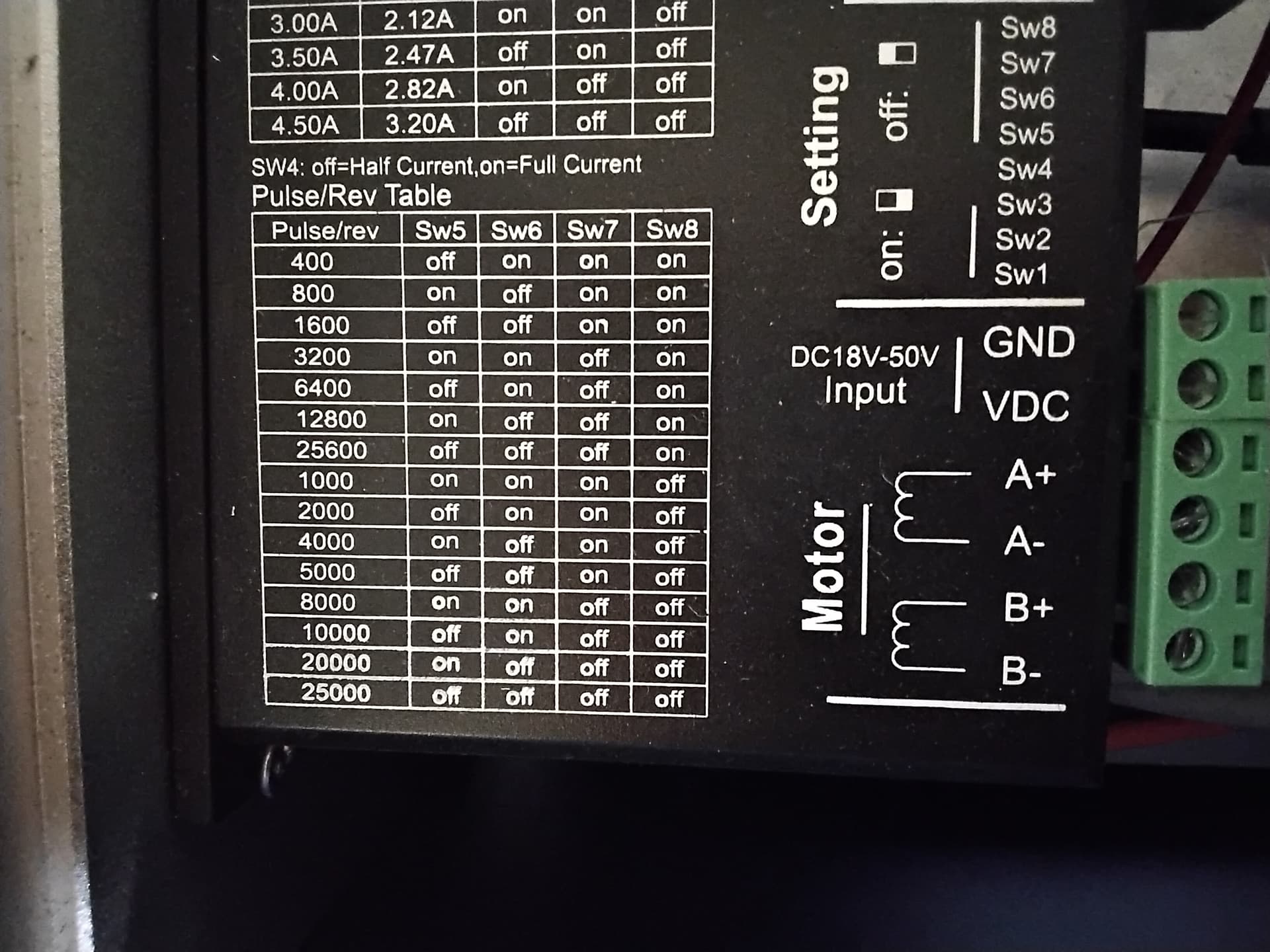
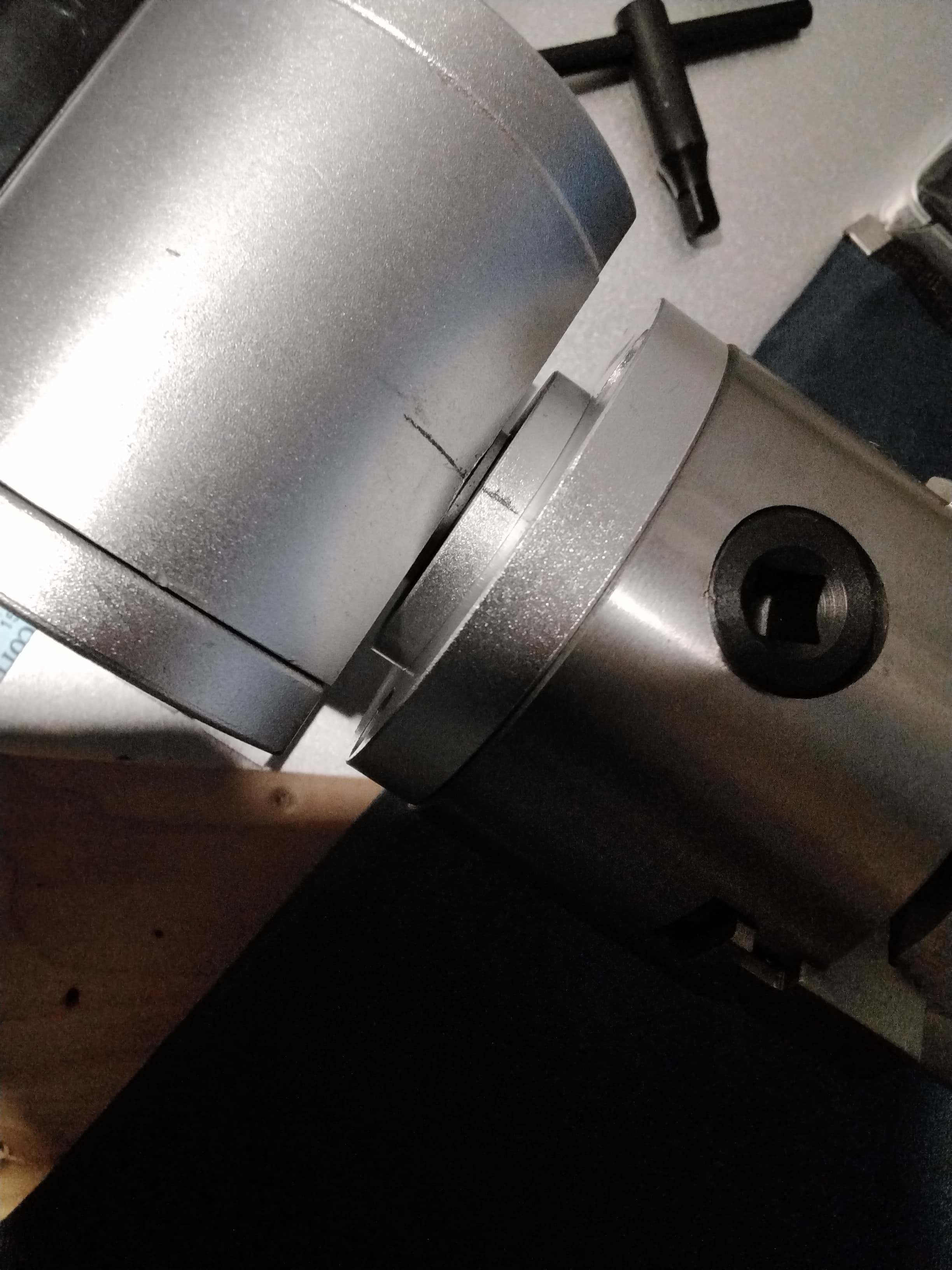
I would go back to the beginning, dip switches and test rotation. Double check dips. Make a good mark on the rotary and run test again. Make sure you are seeing full 360 degrees of rotation. It looks by your circle like you maybe have dips set for 25600 (double 12800) which cuts your angular (and surface) movement by half. Looking at one of my microstep drivers (Not knowing what you have) the dip’s for 12800 and 25600 are the exact same on 6-7-8 and reversed on 5. Difference between 12800 and 20000 is also only one switch, reversed on 8, which would also squish art, by a little less.
This is my pencil line that lines back up perfectly both directions when i run the test button with my pulse setting at 12800.
The only other person i found on the net with a similar problem reloaded his .cor file and it magically started working. But never having used ezcad, i dont have a .cor file to try that.
I have another job, 50hrs a week and 4 kids. So its tough getting out to the shop to figure this out faster. Haha
Maybe ill to mounting it to rotate on x and see if that does anything…
So to run corfile2 requires ezcad and swapping the LB driver for the ezcad driver, unless I’m mistaken. I would suggest getting rotary out of the way, refocus on the table, do a quick check by marking a large and small square on black tape and measure for size and corner to corner, If that comes out correct then not much reason to re-do lens calibration.
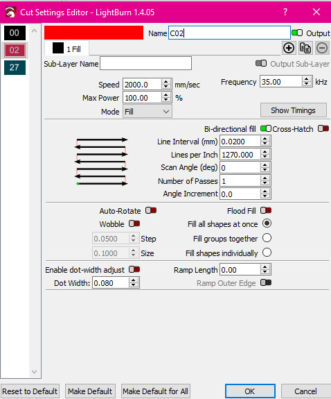
Maybe try a test with a larger slice, like 3.1 mm it is possible that your rotary will not move exactly 0.040mm and that is causing the issue. Doing the math circumference/12800, it should move in increments of 0.0155mm +/- so it stops on either 0.0465mm or 0.031mm, but not on 0.040mm, (all are very tiny movements).
Do you know the amperage on the motor and are the dips set for it?
Something else to try, set LB and dips for 6400 and see what happens.
Just spit balling.
Probably true, although corfile2 is a stand alone application… it just comes with EZCad2… The only time I make off with the spouses computer is when I need to run some of this stuff.
However, I think this is the wrong path anyway. This has to do with the lens correction. Lens is for the lens, the rotary doesn’t use this information.
it works ok with the table
a. galvos and table ok, must be a corrected lens configuration
the test button on the rotary gui in Lightburn performs correctly.
a. if this works all the configuration is setup, with the exception of diameter
Since the only use configurable part that I know of is the gui itself.
I’ve done a lot of stuff on my rotary and I’ve never figured what steps I need, like you have. Guess I haven’t done enough of them.
Corefile runs stand alone but not with LB driver, but yes, easy to have ezcad and driver on a different computer, if I add a new lens or redo an old one i would do it that way rather then swapping drivers back and forth.
Ive always calculated steps, no reason to tell the rotary to stop somewhere it can’t. Then adjust line increment to evenly divide into that. BUT I started with a rotary set for 6400, and doing black on stainless tumblers it would really show the cadence. Last one I assembled has 6:1 ratio so 38400 steps with driver set for 6400, makes a lot less of a difference.
I like using a ratio type rotary rather then increasing the steps on the driver, seems to run a lot smoother. But, have a belt to tension on the downside. Have a worm gear reduction on the rotary table I put together, pretty close to zero backlash.
so in the end i took the lens that came with the laser, which was “set up”, and i added it as a whole new lens. after dialing in the size of my preview projection, buldge, scale andd everything, i simply followed the steps to set my chuck back where it needs to be, loaded the same file and it burned normal.
another weird thing i noticed was my machine was advertised as having a 200mm x 200mm work space, and looking up the info on my lens thats what it says also… but my machine was set to 110mm x 110mm. i dunno if that had anything to do with it, and i dont even care now. im up and running where i need to be.
thanks everyone, and thanks al for recommending adding a new device. looking back… i probably should have just tried another one of my lenses to see if they squished the image also.