The basic configuration of the rotary is the same. The only difference occurs if it’s a ‘chuck’ type or ‘wheel’ (roller) type.
You didn’t mention…
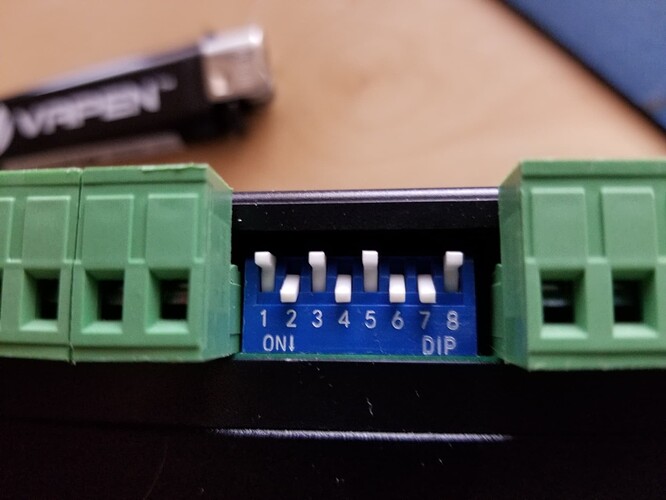
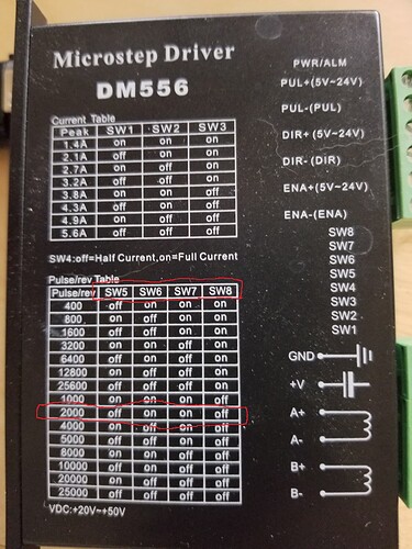
The motor drivers tell you how many steps/rotation the motor takes. Read that off the switches. The placard on the motor driver will tell you the steps/rotation.
Chuck type rotaries rotate one rotation for the motor since it’s connected directly.
On a Wheel type you must compute the gear ration and the driving wheel diameter…
Mine is a PiBurn and is a wheeled rotary.
Translate the configuration to steps/rotation
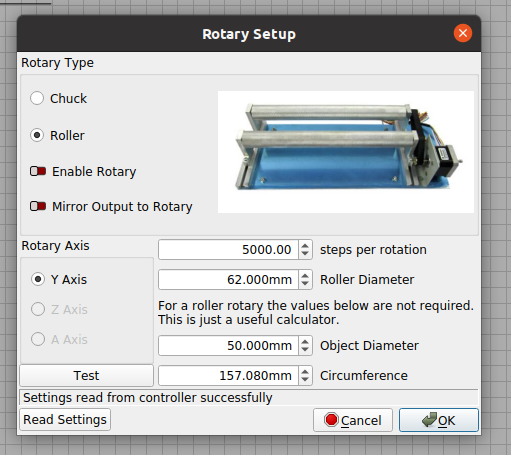
2000 steps/rotation. The gear ratio is 2.5 * 2000 = 5000 entered in Lightburn
For a wheeled rotary you also need to enter the driving wheel diameter, 62mm in my case.

If you’re is a chuck you don’t need the ratio (it’s 1:1), but you will have to enter the diameter every time it changes so the machine can compute the ‘surface’ speed of the object.
Make sense…?
Assume ‘width’ is the X axes direction?
X axes being off is odd since the rotary doesn’t do anything with the X axes. It only modifies the Y axes computations to make it look like a Y table… You did select the Y axes…?
Don’t know what to tell you here… ![]()
Good luck
![]()

