All,
We are learning how to use our rotary head and have had some luck. I also found some pretty good seetings for burning black on stainless, that I am trying to marry with buring stainless on my rotary head. I have a Monoport 50W fiber and and I am using the 200mm lens that came with it. Currently I am running 50mm/sec 25 Freq, and 35 Power. That gives me a good finish on flat stock. When I go to the rotary it starts out good, but looks a little out of alignment. I suspect it is the split size or overlap, but I have yet to find a video or a book that explains the impact of raising or lowering split size or overlap and therefore I am struggling to diagnose corrections due to long run time. I am currently sitting at about 45 minute run. If this blog will let me post a pic, I will post one to show the error I am seeing. Any insight on the best approach to fixing that would be stellar. I also have a fundamental setting question. If I am getting the result I want at 50mm/sec 25 freq and 35 power will I get the same quality at 100mm/sec 25 freq and 70 power? I am trying to figure out if the numbers are linear so I can halve the run time if I have enough power. Is there anything out there on the impact of tweeking frequency to offset speed or power limitations? Any points in the right direction are appreciated.
What causes it to mark (not engrave) is heating of the metal to a certain temperature, creating an oxidized (or annealed) layer that blocks light reflection.
If you change speed the pulses/s will be different and the metal will heat differently, not necessarily resulting in the same oxidation or color.
I’d say it probably won’t be directly applicable. Nevertheless, I’d encourage you to try.
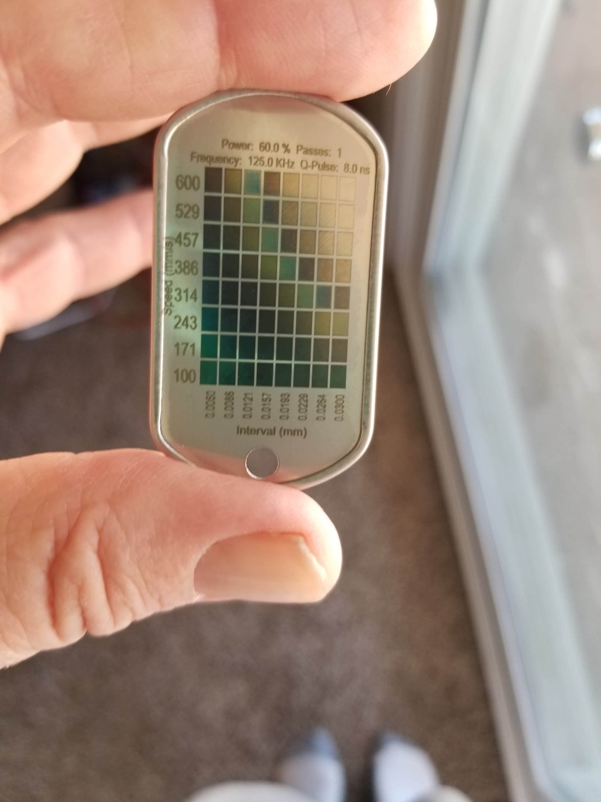
I usually change the interval to get my widest range of color or markings.
I run a split size based on a multiple of the interval. The ending split size would be how far the fiber can go around the curve and still maintain focus or within the proper depth of focus (dof) of the lens I’m using.
The less you have to wait for the object to move, the faster the job… Every step of the rotary takes a lot of time, Lightburn has to tell it to move, then wait for it to complete then scan the next split size where it has to move the rotary again. The galvo is lighting fast compared to rotating an object, the more you can do with the galvo and less with the rotary, the quicker the job.
If you have an interval of 0.02mm then a split size of something like 2mm or 0.2mm should work… A long enough lens, with a large diameter object might do OK with a 20mm split size.
These intervals are very small and you have to keep in mind that you could generate a step that is too small for the motor, so it doesn’t step and then makes up for it… This happens and there is math that goes along with it.
I’ve done fine using a split size of some multiple of the interval. I don’t use overlap, so can’t help you there…
What Jack said.
I’ll take it one further looking at your photo you have a couple problems. Assuming the jogs in your curved lines are around the splits, I would say your diameter is not entered correctly. The closer the better, and use the largest number when tapered. OR your steps are not set correctly, but either way, you can get a lot closer / smoother angles and curves with a little more work.
Another thing I like to do is divide the total steps into the circumference and use multiples of that number for your line increment and split. It doesn’t help when the stepper is given instructions to step to positions it physically can’t.
Your parameters look good, might drop the power a little or increase speed. You didn’t post line interval, but to pick up speed defocus 4-5mm and increase your line increment, add a little more power. First though get your rotary settings dialed in and clean up those curves.