Rotary Help Needed for Ruida RDC6445G(EC)

LightBurn v1.4.00
Ruida RD6445G(EC)
Chuck type Rotary with its own wiring to additional driver M542

Latest Firmware for Ruida RDC-V15.01.30 (for U-Axis upgrade)

I have the dip switches set correctly and the rotary turns exactly one revolution when called upon to do so, so the steps/rev are also correct.

There’s a couple of things going on that aren’t correct though.
When I plug in the rotary to its 4-pin aviation connect (goes to M542) and enable the rotary, the Y-axis is what moves if I’m framing the design. Plus the Y-axis moves at a very slow speed as if it’s using the steps/rev that are actually for the U-axis (haven’t confirmed the amount of movement of the Y but it’s definitely not correct.
I have to disable the rotary, power down and disconnect the U-axis then power back on to get the Y-axis moving correctly again.

Another thing is that in the rotary setup, the only axis that’s not grayed out is the Y-axis so I can’t actually tell LightBurn that I want to use the A/U-axis. Doesn’t matter whether I have the rotary enabled or not, the others are still grayed out.

Oddly, even if I don’t have Enable Rotary checked “ON”, the rotary will still rotate via the buttons.

I’ve installed 4th axis for rotaries on other CNC machines in the past and I’m certain I’m overlooking something simple but any help to clear my noggin’ would be appreciated!

Just to state the obvious, I’m wanting to still have full functionality of the Y-axis to be able to position it over the rotary table via the control panel or through LightBurn. Having said that, I don’t want to disconnect the Y and attach rotary to its port. That’s the whole reason I went to the trouble to get the A/U axis set up in the first place. Lot’s of time and a little bit of money to get this going but I’m at a loss as to how to proceed.

Yes, I think I’ve read almost every post out there over the past month or so on how to set up a rotary with the Ruida and settings in LightBurn.

I keep thinking I’m really overlooking something so any insight would be helpful.

TIA

EDIT:
I dropped back to RDC-V15.01.22 and reset the controller, but the A/U is still grayed out in LightBurn.
However, sending the vector tile to the controller now has just the X-axis moving and the rotary turns although not nearly enough. So I’m guessing I’ll need to adjust the steps/rev to account for something. Not sure why that needs to be done though since I know the number of steps/rev worked before.

EDIT #2
So I wound up resetting the steps/rev to another value after some calculations. But this was only after doing a calibrate axis routine on the U-axis and seeing absolutely no changes in the amount the rotary spun. I’d tell it to move the circumference of the chuck for one revolution and it would only move a portion of the rotation. I’d mreasure that and input it in the actual field and write the changes to the controller. Nothing would change. The rotary would still spin the same amout (not full rotation) regardless of what I told it.

Also, I still have grayed out A-axis radio button as is the others.

I still can’t get control from LightBurn to run the file. I have to Send to the controller, then run it from there. At least it appears to be working at the moment. Tomorrow I’ll venture in to doing some test runs on some cheap tumblers to see how it’s getting along.
Fingers crossed.

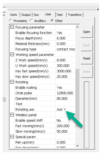
The RDC-V15.01.30 firmware for RDC6445G should work fine. This version builds upon the firmware patch Marco Wong (LightObject) instigated/lobbied for, and allows the choice for rotary output between ‘Axis Y’ and ‘Axis U’.

Note: When using firmware v15.01.30 you currently have to use RDWorksV8(8.01.60) to change the controller-based ‘Rotating axis’ setting to ‘Axis U’ e.g.

In LightBurn, the rotary axis will remain as Y, because from LightBurn’s perspective nothing really changes with the command output - I don’t think the controller allows coordinated X/U commands anyway.

My understanding is that when rotary is enabled, even if rotary output is set and connected to U-axis, the U-axis firmware settings are ignored and pretty much all of the settings for Y-axis will be still used by the controller.

The Y-axis setting that will change will be ‘step length’, as will be automatically determined internally by the controller based on it’s rotary parameters; ‘Circle pulse’ (labelled ‘Pulses per rotation’ in LightBurn ‘Machine Settings’) and ‘Diameter(mm)’, which are uploaded to the controller via the ‘Rotary Setup’ dialog in LightBurn.

Hopefully this explains why you get some odd behaviour from Y axis which is normal when in rotary mode. The control panel at the machine should be your friend when in rotary mode to position, set origin, frame and start the job that you sent using ‘Send’ from LightBurn and ‘Current position’ or ‘User Origin’.

This topic was automatically closed 30 days after the last reply. New replies are no longer allowed.