On my 60W Red/Black VEVOR CO2 Laser i have from factory an “Roteray Interface” Plug in the right inside in my Laser. (under the Honeycomb).
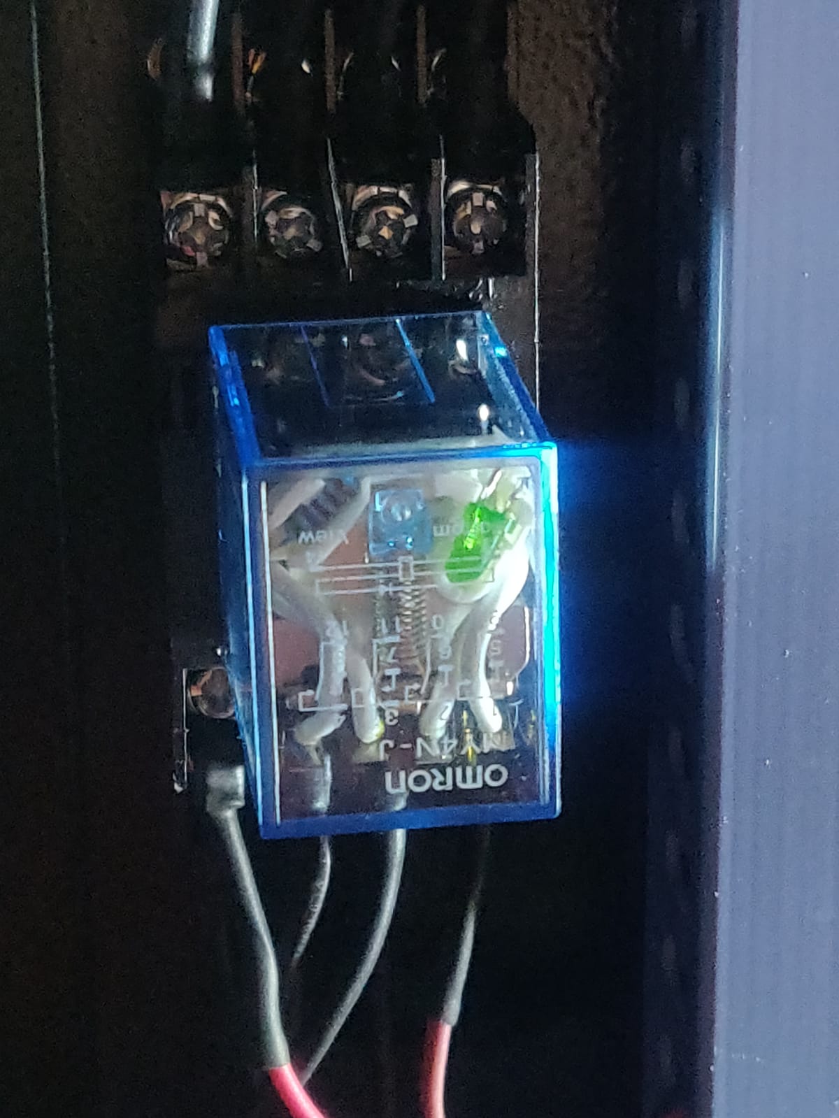
I followed the cables from this GX16 4 Pin Connector and they are wired to a Relay.
I only have two Stepper driver in my Laser.
Can somebody help oder explain me how i can activte this Rotary Interface?
I want do buy a Rotary but dont know how i can activate this.
If i active “Rotary” through Lightburn i still can move the Y Axis back and forwards but very slowly.
I also think that my Y Axis and the Connector from my Rotary Interface are connected together.
But i could not find out how i can activte the Relay/ the Rotary Connector?
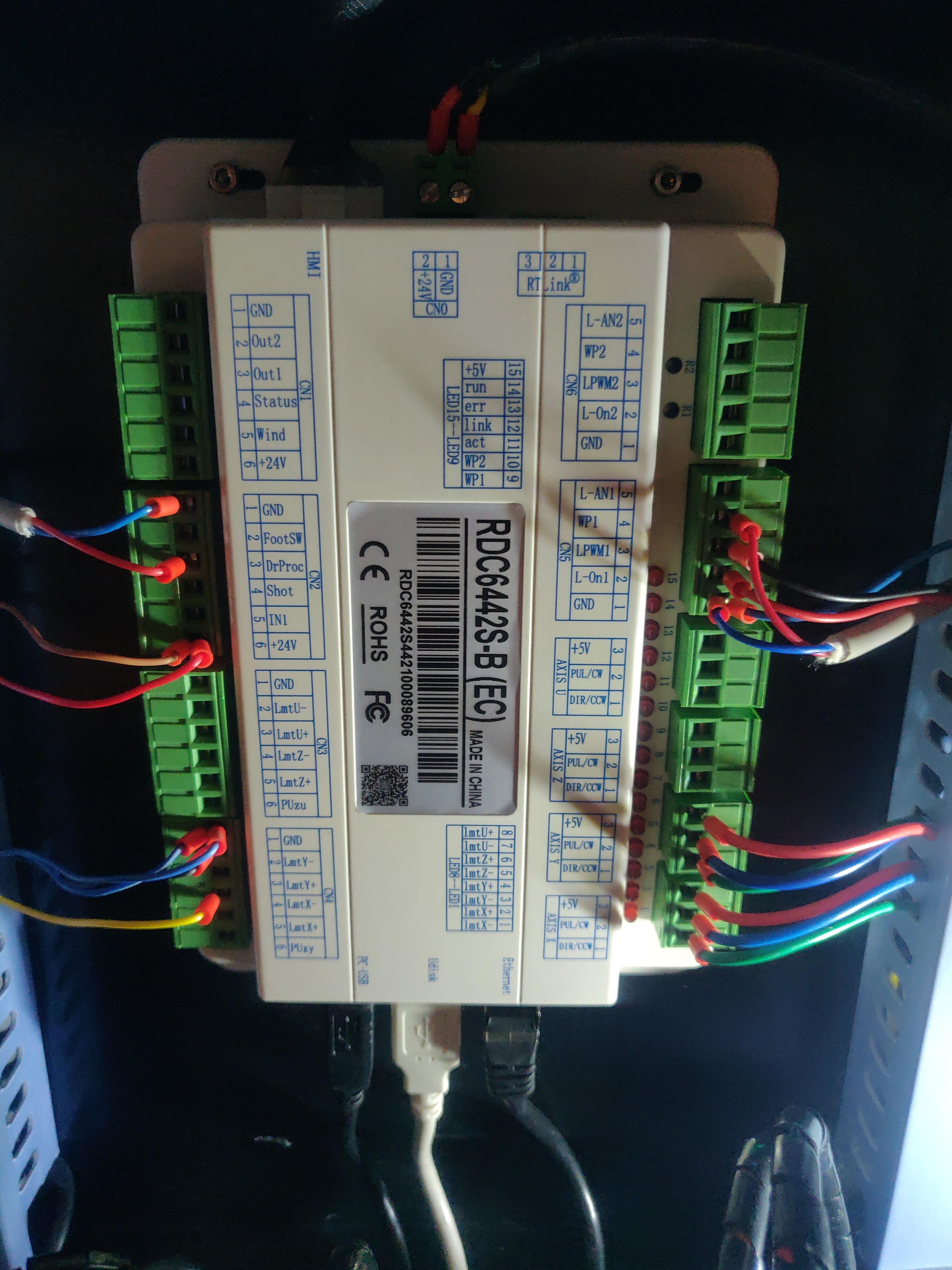
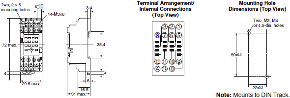
You should find there are 12 attachment points for the stepper wiring. Four from the GX16 4 pin connector. Four of them should travel to the Y stepper driver and four should travel to the Y stepper motor. There should also be a power connection and ground, which would be switched by an external switch or a data driven switch.
I have the equivalent manual switch, with all 12 points, connected in the manner described above. General advice from the internet indicates to switch from one device to the other only when power is off. In the case of a relay, I am uncertain how that would be accomplished safely.
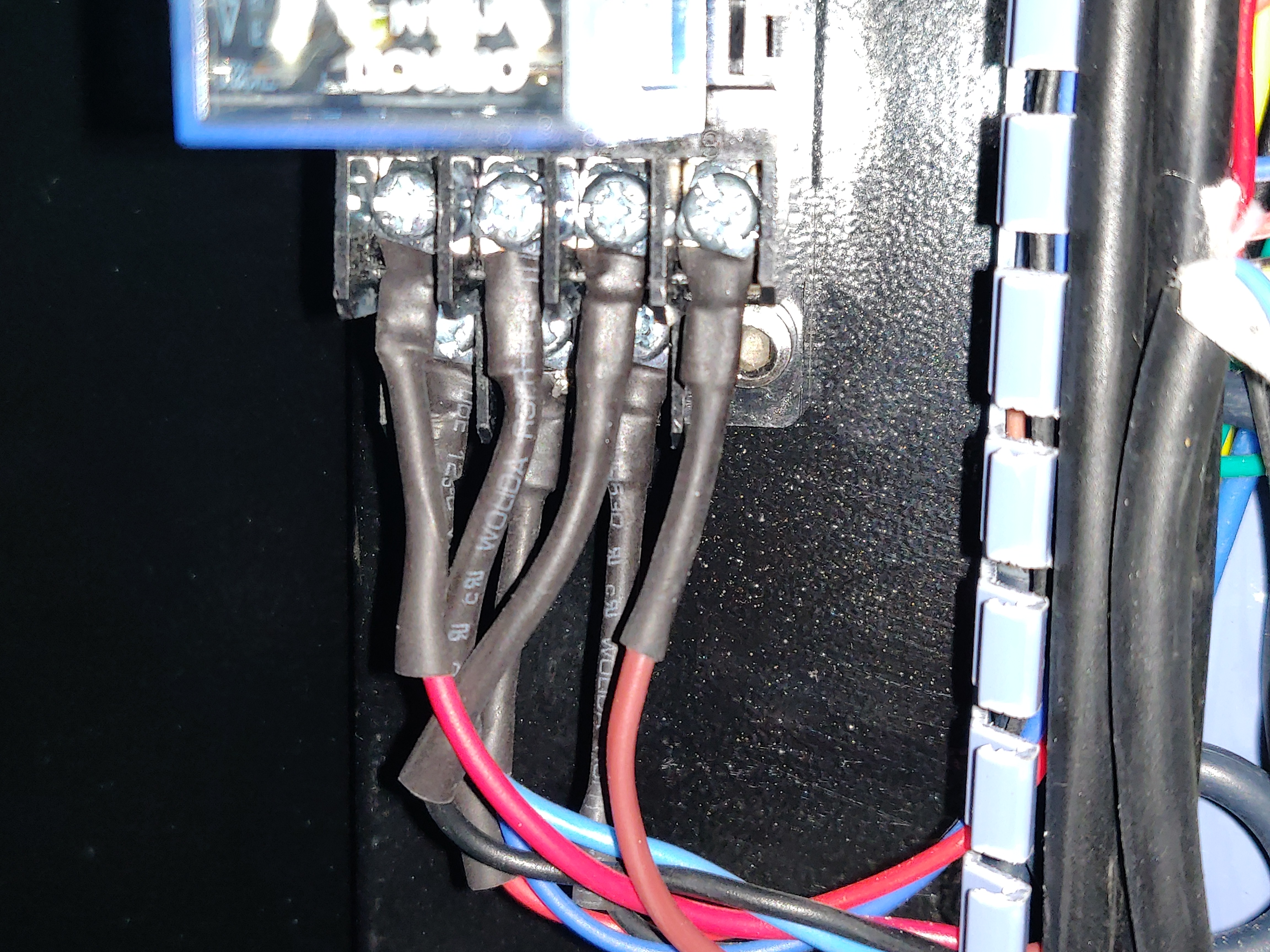
If you can identify the power and ground connections and trace the wiring, you may find additional useful information. If possible, please photograph the wiring diagram on the cover of the relay, in such a way as to make the diagram as visible as possible.
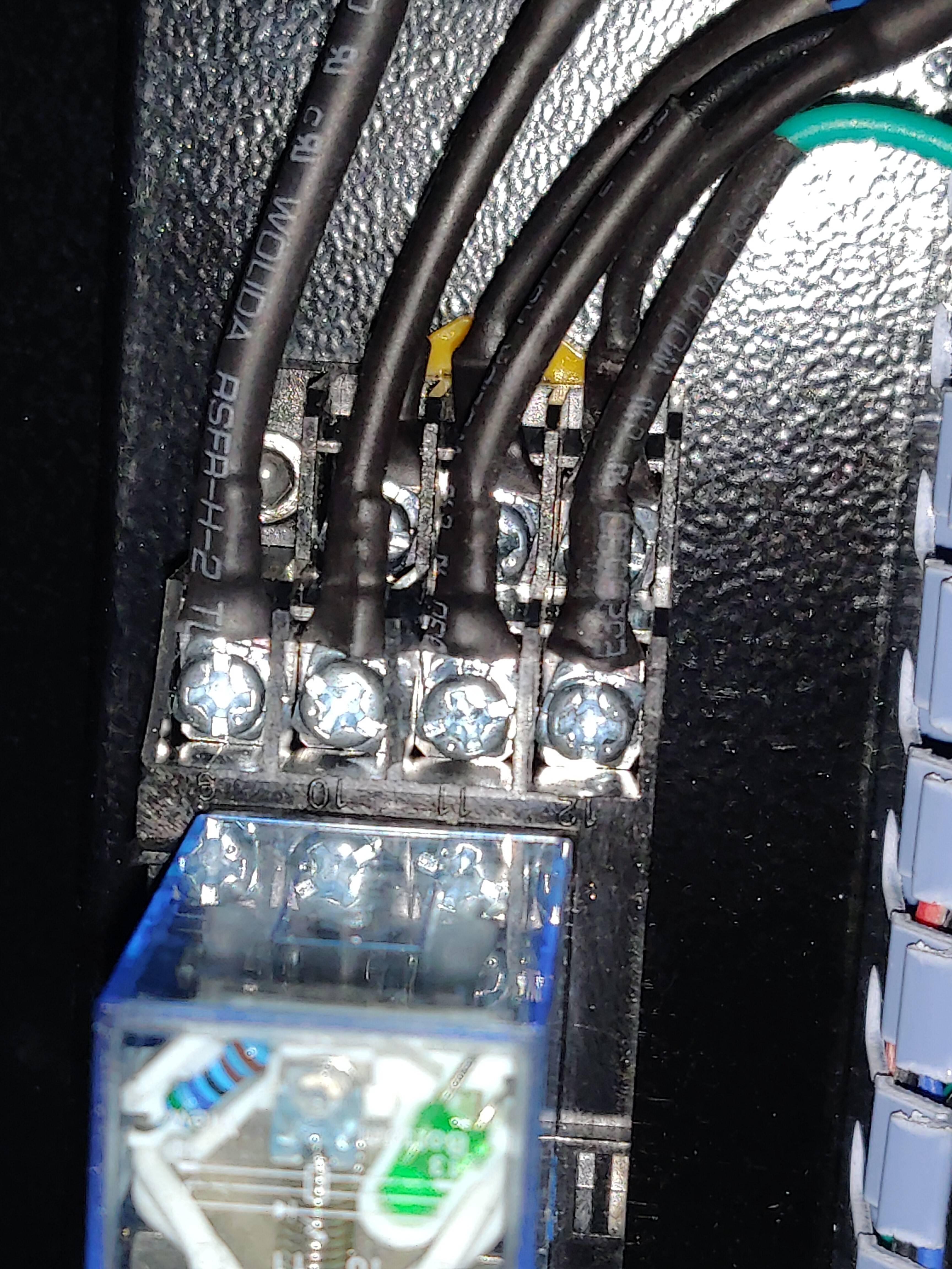
9-12 will go to the stepper driver
1-4 will go to either the y-stepper motor or the rotary ports
5-8 will go to either the rotary ports or the y-stepper motor
13 and 14 are the switching power
The spec sheet shows it to be 24 volts dc and the coil is non-latching. This would imply that the controller will trigger the change when required and also implies that doing so while powered is acceptable to the controller.
You should discover that 13 and 14 are connected to the controller. If not, I’m at a loss to address this.
Changing the device to be active is the part I for which I do not have an answer. I am hopeful that the wiring for the power to the relay goes to your controller. If it does, there must be a method in software to select the correct device. Because the relay is non-latching, the coil will be energized only when the rotary is in use and you should hear a click from the relay, even without a rotary device connected, once you direct the controller to change devices.
The information I was able to locate from the internet is minimal. Nothing about the rotary switching and no manual for operations, of course.
I’m hopeful someone with a similar machine or a better understanding of the controller will chip in and comment.
yes I did, but honestly I don’t quite see through it yet!
I know that the plug goes from the bottom of the rotary to the relay but everything else is still very confusing. Also because of the whole cable channels which are difficult to open.
In the software (also inRD works) I couldn’t find an option either
I have not found/seen a trigger in RDWorks or in LightBurn either, to address the rotary. I don’t think that simply connecting the rotary will cause the relay to close, either.
I’d be more concerned about the idea of switching an active stepper driver while power is on and feel that using the relay is a bad idea in general, unless someone smarter than I cares to jump in.
If you can determine that the wiring from the rotary connector leads to the relay on the above noted terminals and that the wiring from the controller y-axis leads to the noted terminals and that the y-axis stepper motor leads to the correct terminals, you may be better off changing to a 4 pole double throw mechanical switch. I purchased one and installed it with minor complications. It’s loaded with so many wires to make it look like an electrical porcupine, but it’s really convenient.
If 5-8 go to the rotary connector and 9-12 go to the stepper driver, then 1-4 will go to the y-stepper motor, as process of elimination. The three wires on each side are an unusual way to manage the connections, but I think you’ll find that of the six (3 * 2), four of them are 1-4 and the remaining two are 13, 14, which still presents a puzzle.
I found this reference, which has the offset tab shown in your photo, although inverted in the picture. It indicates that pins 14 and 13 are on the top in your last photo, the two screws to the right, adjacent to pin 4, while 1-3 are on the bottom.
If you can trace 13 and 14 to a switch or to the controller, you’re one step closer.
so if this reference is right then PIN 13 goes to a stepper Driver 24V -V
but i could not terminate where PIN 14 comes out
EDIT: I have found the Solution!
In the Front of my Laser i had two Switches (Protection Switch, Lighting Switch) and Emergency OFF!
Between the two little Switches, there was a “dead cover”…
I found two cables labeld with “Plane Rotary” in a Cable Hose near under the Display, even with the yellow china Label.
I also found the switch, which was unfortunately damaged and therefore probably “hidden” in the cable hose…
So i put a new Switch, attached the two cables, removed the “dead cover” and mounted in it.
Then i activated the Switch, powered on the Machine and the LED on the Relay was GREEN!
But when the Laser is on and a deactivated the Switch, the Stepper Driver got an RED LED?
If a Power off and Power on the Machine again with the deactivated Switch it turns GREEN again.
Could you say my if this is normal?
Should i only activate and deactivate the Switch when the Machine is off?
Switching from rotary to flat should NOT be an issue UNLESS you are in the middle of a job
The power from the controller to the relay to the stepper in use is only effected from the relay to tbe chosen stepper. I don’t see where switchjng from one to the other will be an issue. UNLIKE mine where I ha e tk unplug one from the controller and plug in the other. When I do that, I am removing power from the controller and reconnecting it. With the relay, you should have CONSTANT power to the controller. What is being switched is the OUTPUT from the controller.
This is just my opinion. Of course I could be wrong but ai don’t believe so.
Stepper drivers are ‘smart’ the first moves of machine axis allow them to analyse the attached motors characteristics. Switching between a motor and open circuit will likely trigger a fault in the driver. Even with two identical motors bought at the same time from the same manufacturer will likely trigger the same outcome.