If 5-8 go to the rotary connector and 9-12 go to the stepper driver, then 1-4 will go to the y-stepper motor, as process of elimination. The three wires on each side are an unusual way to manage the connections, but I think you’ll find that of the six (3 * 2), four of them are 1-4 and the remaining two are 13, 14, which still presents a puzzle.
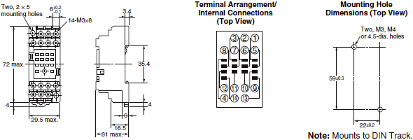
I found this reference, which has the offset tab shown in your photo, although inverted in the picture. It indicates that pins 14 and 13 are on the top in your last photo, the two screws to the right, adjacent to pin 4, while 1-3 are on the bottom.
If you can trace 13 and 14 to a switch or to the controller, you’re one step closer.