Rotary Setting Have No Effect?

When working with the rotary there is one acceleration rate for the rotary axis and two speeds related to the rotary axis. The traverse speed and the engrave speed. Working with the speed in the Move window is like a different engrave speed, up to a point.

Please post the value for $111, the engrave speed and the speed in the move window.

An aluminum can is really light and can be somewhat slick. Excessive acceleration combined with high speed motion allows the can to slip for more time on the rollers and move less than it was told to. The aluminum can doesn’t have the benefit of the toothed belt to force it into a precise location.

The engrave speed, usually slower, will spend less time accelerating and will slip less.

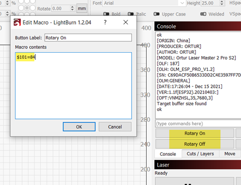
When the Rotary mode is enabled it recalculates the needed steps per mm based on the info available to LightBurn in this window. Turning the rotary tool off turns the steps per mm back to the $101 settings. With the rotary mode off, please return the $101 setting to what it was.

First thing I would offer for troubleshooting is to set the Y axis acceleration to half its current value. What is the current value for $121?

The settings report available through the console window by entering $$ may be of benefit here. Please copy and paste the report into a reply here.

I’m not as familiar with the version you’re using. I can download it for testing and my engraver / rotary may be similar enough that some of the settings will apply.

Let’s start with speeds and accelerations first.

Yeah. I get that the can is pretty light. I don’t think it’s slipping, though, because it is pretty repeatable as far as moving over 0 and back to 0 multiple times in a row. And when I man manually set $101, it works like it should.

Here is the $$ list:

$$
$0=10
$1=25
$2=0
$3=0
$4=0
$5=0
$6=0
$10=1
$11=0.010
$12=0.002
$13=0
$20=0
$21=0
$22=0
$23=0
$24=25.000
$25=500.000
$26=250
$27=1.000
$30=1000
$31=0
$32=1
$100=80.000
$101=80.000
$102=250.000
$110=6000.000
$111=6000.000
$112=1000.000
$120=1000.000
$121=1000.000
$122=10.000
$130=410.000
$131=400.000
$132=200.000
ok

I’m with you on this, and i appreciate how attractive that repeatability is.

For the moment, consider the idea that three equally long travel commands at three different speeds would all move the same distance if they didn’t slip.

Not exactly… a stopwatch may offer another perspective.

$100 is x Steps / mm
$101 is y Steps / mm

$110 is x (max rate mm/minute)
$111 is y (max rate mm/minute)

The default for traverse speed is the $110, $111, $112 values.

I would be interested to know if you’ve cut your speed inadvertently by changing your steps per mm.

This may be worth review:

Are certain the diameter of the driving roller is 12mm? did you use calipers? I’m guessing it might be a fraction smaller eg 11.43mm?

I did. For some reason, I get different measurements up and down each roller, but it averages out to 12mm, which is what the company that makes the rotary says to use.

I can get the basics of that document, but once it starts getting all mathy, I tend to glaze over :slight_smile:

When you said “not exactly” were you referring to my claim that the steps are 84 or to my manually changing $101 to 84 and getting the correct results? I’m getting the steps from the manual that came with the rotary.

I’m not sure I understand the stopwatch, either.

It’s pretty crucial to get the roller measurement correct, just try 11.43, I think (I just cant test it right now) that will cause the background calculation for steps/mm to increase and bring your 201 to 210. And as @JohnJohn mentioned leave $101 at 80, since when you turn rotary mode off you will need it to be correct.

1 Like

I will try that. I’m burning a tile right now, but as soon as it’s done, I will see what that does.

1 Like

@JohnJohn @NicholasL

So… I gave that a try, guys and like I suspected, it had no affect at all. For some reason, nothing I put in that dialog has any effect whatsoever on the rotary.

Changing that value, though, if it had worked, I would have thought that that would be more a workaround, though since in LaserGRBL, changing $101 is what the manual says to do when using it with that program. I was thinking that Lightburn must be modifying that parameter automatically when you toggle “Enable Rotary,” No?

Anyway… :frowning:

It is curious that making large changes to roller diameter or mm/rotation when in rotary mode with roller selected does not affect your output in any way. I haven’t tried testing this in your version 0.9.22, but I suspect that may be part of the problem, and I would encourage you to upgrade.

Anyway, if you use $101=84 and the rotary works fine then that is a perfectly acceptable method of setting up the rotary, just make sure you do not also enable the rotary axis in LightBurn. And of course you will have to put the original $101 value back again manually afterwards.

Just for the hell of it, I downloaded the trial of 1.2.04 and tried that on a different laptop. Same result. I can do the $101, but I know with my memory, that is going to be a recipe for disaster. :frowning: I appreciate your time, anyway.

To save typing the command, you can save it to a macro button:

Just right-click one of the macro buttons, rename it then just enter the console command e.g for “Rotary On”

image

That method will work fine but if you are still interested in using Rotary Mode, here is another method you can use to test LightBurn to see if the rotary output is being changed correctly:

First make sure $101 is set back to 80 and enable rotary is OFF.

  1. create a 10mm square for simple line output and use “Save GCode” to file: 1.gc

  2. enable rotary with a 12mm roller with 37.7mm/rotation

Now output the same 10mm square to GCode file: 2.gc

Compare these two files, they should be the same

  1. enable rotary settings 12mm roller with 39.58mm/rotation

Now output the same 10mm square to GCode file: 3.gc

Compare 3.gc with the first two files, it should be about 5% larger in Y values now.

Is that the case for you? I would be very surprised is the GCode output was no different.

Now I’ll explain the 37.7;

For the roller, our documents encourage you enter the roller diameter and then hit “Test” until you can discover and enter a value which will turn the roller 360degs and enter this figure into “mm per rotation”.

In the background, LightBurn knows that if the roller diameter is 12mm then a 360deg rotation of the roller should happen if you “Test” it with 12mm*pi (37.7mm).

If you entered 37.7mm absolutely nothing would need to change. Hence the above output results for file 2.gc.

If you enter a larger amount than 37.7 e.g. 39.58 for mm per rotation then LightBurn will immediately know that the scale of the axis is different because it needed to move the axis further than expected in order to get to 37.7mm. At this point, with the values of 12 and 39.58 entered, enabling Rotary Mode will add 5% to all Y axis values to ensure the final output size remains correct - hence 3.gc.

If you wanted to make this change manually (and NOT use Rotary Mode) then you would need to increase $101 resolution (Y steps/mm) by 5% from 80 to 84.

In your case, since it was hard to measure the roller exactly, I was thinking you could try this to get your rotary settings dialed in using the can;

-Enable rotary mode, put your known-circumference can on the roller and enter 210mm in the mm per rotation and roller diameter size at around 12mm, use “Test” and then adjust “roller diameter” until the can rotates 360degs exactly.
-Now draw a 210 mm vertical line, frame it, adjust the “mm per rotation” down (start at around 41) until the can rotates 360degs exactly.

Optionally - lightly burn a line for the above tests - it might help to add little horizontal marks to the line ends. e.g: image

Oh, OK… I can do that with the macros.

I actually did try that line method the other day. What I did was create a 210mm line and the freaking thing just kept going! I think drew like, three paths around the can? I finally managed to get a 100mm line to draw a 213mm line around the can.

The other suggestions, though… they don’t have ANY effect on the rotary. I accidentally left “Rotary Enabled” enabled when I started a flat job and it did seem to affect the movements of the laser over the bed. Once I turned that back off, everything was ok. I found that really odd…

This topic was automatically closed 30 days after the last reply. New replies are no longer allowed.