The steps per rotation and roller diameter change in the middle of the job, resulting in the artwork coming out squished on one end. Has anyone else encountered this issue, and how was it resolved?
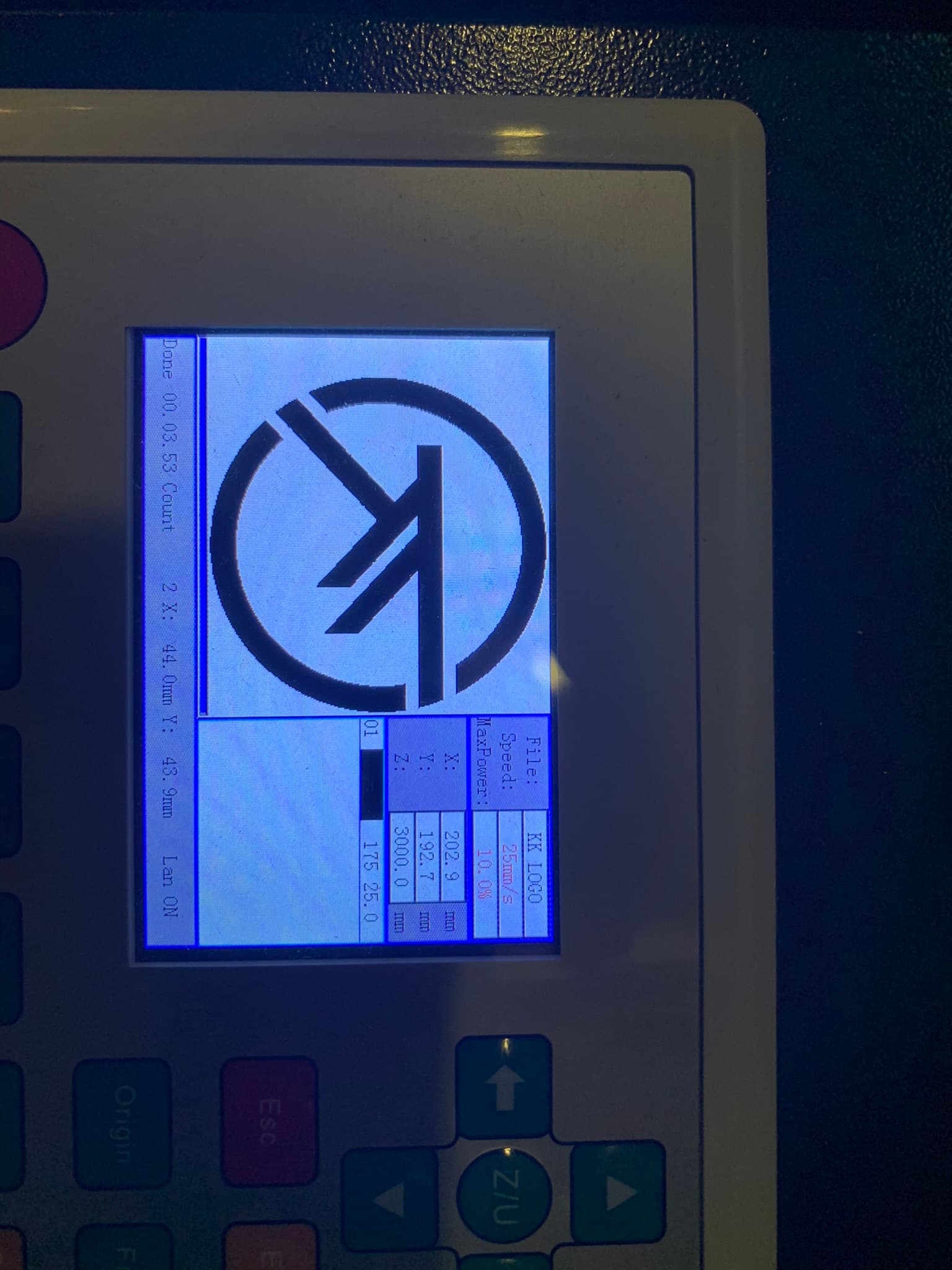
I’m using an OMTech 80W Red and Black, with an OMTech 4 wheel rotary. I have dialed in the steps per rotation to 3000 correctly and measured the rotary wheel diameter at 67.56mm. The problem is inconsistent with some jobs coming out fine, while the majority of jobs are no good. I’m communicating to the laser via LAN, and initiating the print from the software.
The reason why I initially thought that it was the software is that the “steps per rotation” and “Roller Diameter” settings in the “Rotary Setup” changed from what I entered (3000 and 65.57) to (360 and 50.00) at the end of the job.
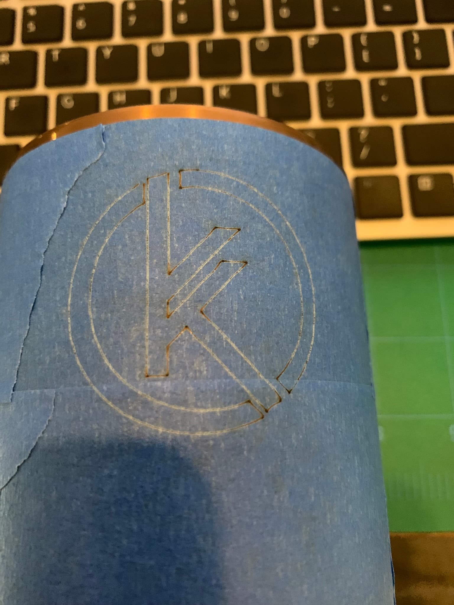
It may not be the software as I tried running it directly off the laser and that resulted in problems as well. Now I’m totally confused as to why the prints are in consistent. I don’t believe that it’s the design as I attempted the same design with as a line on tape (with lower power settings) and it came out as expected.
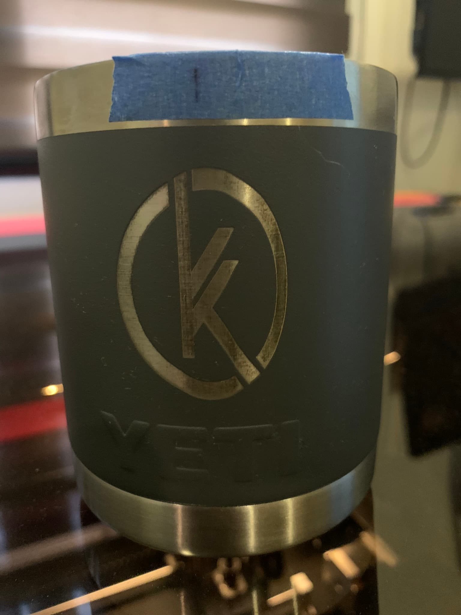
The problem is that the image is supposed to be circular, but is not. The height is correct (x axis motion), but the width (rotary motion) varies during the job.
There is another problem that I discovered, the image is printed on the cup a little further down than it’s supposed to be. I’m not sure what’s causing the origin to start at a slightly different place on the rotary axis than where it’s supposed to start.
I’m beginning to think that I may have a defective rotary.
Those are the default values in the user interface. It’s quite likely that the communication from the controller didn’t work, and they were simply left as they were instead of having the values from the controller displayed there instead.
If that happens, you should see a message saying “Communication with controller failed” or similar at the bottom of the rotary settings window.
I did a test, similar to the one outlined in the following video.
I essentially drew two parallel lines exactly 100mm apart and burned 100mm lines from the start line to the end line. I played around with the “steps per rotation” number until the start and end lined up where they were supposed to. As a point to note the 100mm line was drawn on a flat surface, so I know that it’s a circumferential measurement.
The rotary wheel diameter was measured using vernier calipers. I trust the measurement, as I performed it 4 times (90 deg apart on each of the wheels) and it was approximately the same for each.
Before the start of the job I get the message “Settings read from controller successfully”, with the values that I have entered (3000 and 65.57). The job sometimes starts out alright and changes in the middle. At the end of the job is when I see the values reverted, but I would admit that I haven’t paid much attention to the status when the job is done.
Watched (or most of it) the video… I think it’s being handled backwards by the approach but if it worked for you … great …
These set up rather easily once you understand how they work…
There is no need for knowing the diameter other than with the artwork with a ‘wheel’ or ‘roller’ rotary. It has no effect on how the machine works and complicates his ‘setup’…
IMHO… start at the begging and when you get to the analog stuff you can make adjustments.
This is the basic setup, which is where the video should have started… it works fine most of the time…
The system is digital up to the motor output shaft. After that it’s a ratio to turn the drive wheels, which you probably can’t change and the driving wheel diameter, which can change and the adjustments should probably occur there.
If it’s working for you … great…
You don’t need the diameter to test it either. Put your tape on and draw your 100mm rectangle… it should be 100mm no matter what diameter… the Y axes should translate directly to your ‘object’…