Rotary Steps per revolution has changed?

Verily it is written: Hell hath no fury like that of an unjustified assumption.

And, wow, I am so good at those … :grin:

My KT332N manual claims it has a dedicated rotary function:

U axis function configuration :The U axis can be configured as a platform, a feed axis, or a rotation axis.

However, that option appears nowhere in the console Menu choices nor the LightBurn Machine Settings list, so it’s probably buried even deeper in the firmware, where only the vendor’s setup program can go.

On my machine, the U axis drives the platform motor, which is what I’d call the Z axis; there are only U axis terminals on the back of the case. Given the lack of the config option, there are no other choices.

Based on that manual hint, however, I’d assume the controller could use the Rotary info to control the rotary motor according to the U axis acceleration / speed values (at least). Whether it would also pay attention to the limits & suchlike is an open question.

Which may explain why the LightBurn GUI goes through such contortions: there’s no way to tell exactly what the Enable Rotary function will do.

On my machine, with a rotary plugged into the Y axis and the U axis not available for rotary operation, the controller’s Rotary values likely have no effect. On somebody else’s machine, with a different deep vendor config, the U axis would spin the rotary motor like crazy.

However, LightBurn has options to select only the Y / Z / A axis for rotary control, with all but the Y option unselectable here, so I assume the Y axis hack is the “standard” way of making a rotary move and nobody uses the U axis.

LightBurn probably sets the Rotary parameters in the Ruida config, in the hope they might do something. In my machine, they do absolutely nothing, but ya never know.

In my defense, you were getting kinda salty about your background and methodical approach, so I pretty much assumed you’d RTFM and didn’t need handholding after I aimed you at that section:

We would like to specifically call out the Vendor Settings section that will appear for Ruida controllers. These settings are typically set at the factory where your laser was manufacturered or configured and it’s best not to touch any of these unless you really know what you are doing.

Nah, I’d never overlook anything that obvious, either.
:grin:

I appreciate the help. I AM extremely methodical (and also salty), but that doesn’t mean I can’t miss something. In reaching out for help, it pretty much announces the fact that I don’t claim to know everything… :wink:

I probably could have worded my suggestion better. Instead of “It might be good to mention…” I could have said “The thing I was missing…”. Not to dig the hole deeper (as I reach for my shovel), but it would be good to mention when some access requires passing through a big ole “warning” dialog… Just sayin’…

I have never found an auxiliary stepper port (U-Axis?) anywhere “accessible” on the machine. It seemed pretty obvious that I was expected to use the Y-Axis for this (based on plug placement and availability). …just like my last CO2. Additionally, since it all works as expected via Lightburn (hot plug stepper resolution variations aside), it’s pretty clear that’s what expected (via both software and hardware).

“RTFM”… Grrrr!

Just because I missed something in the manual, doesn’t mean this wasn’t a viable question for the forums…

In the end, I’ve found this forum to be a lot more useful than “RTFM”. (Thats why I posted) There are a lot of details and nuances being discussed here which are not addressed anywhere in the manual. (IE: https://forum.lightburnsoftware.com/t/uv-jpt-galvo-parameter-selection-qpulse-vs-freq-with-inversion/107899/1). When my rotary resolution was behaving erratically, I took it here and I think we’ve developed a workable hypothesis (hot-plugging). I don’t expect that is anywhere in the manual either…

But again, thanks for all the help!

1 Like

Oh, not at all. Hang around here for a while and you’ll eventually meet a hypergolic newcomer who asks for help while being so knowledgeable as to reject all responses as being obviously incorrect. I try to scamper beyond the blast radius before those situations go off. :grin:

Weird, huh?

In the CNC world, the UVWXYZ axis move linearly, with U parallel to X (and so on), with ABC axes for rotary motion, with the A axis parallel to X (and so on).

So the stepper motor terminals on various controllers sport these labels:

  • Ruida RDC7132: XYZ (three motors)
  • Ruida KT332N: XYU
  • Topwisdom TL410: XY(Z/U/V) (only three motors)
  • Ruida RDC6442 & 6445 controllers: XYUZ (four motors)
  • Trocen AWC708: XYZUVW (yes, six motors)

Note the complete absence of a rotary axis labeled A (or BC, for that matter). One might reasonably assume no lasers have rotary axes, but …

It’s covered by the universal rubric: "If it hurts when you do that, don’t do that. :wink:

First we have to confirm that was “what hurts”. That will take a little time. I ran for quite a while using my former process (hot plugging) without any ill effects…

But, GOT IT, thanks!

What in the wide, wide world o’ sports is a goin’ on here?

1 Like

I think this is how the magic happens in Ruida-based lasers …

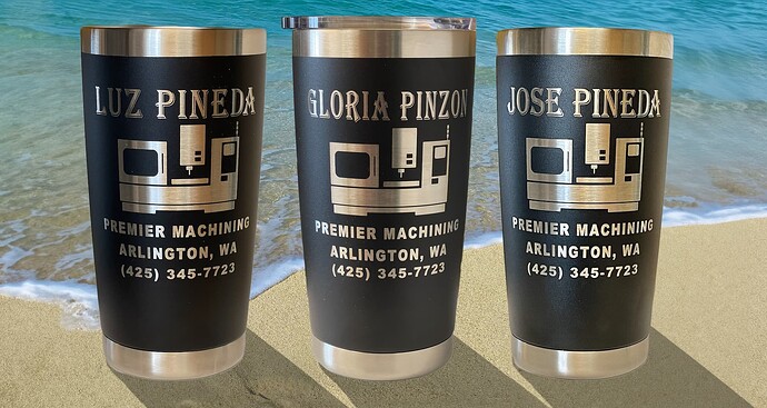
Start with the pattern you’re engraving:

  • The width runs along the tumbler axis (top - bottom)
  • The height gets wrapped around the tumbler (left - right)

LightBurn knows the height of the pattern on its workspace, because it knows the coordinates of every vector / image point to be burned. You drew the pattern with that height (and width) based on how you want it to look on the tumbler.

You tell LightBurn:

  • The number of steps required for one roller revolution
  • The diameter of the drive roller → roller circumference

LightBurn divides the pattern height by the roller circumference to get the number of revolutions the roller must make to move the pattern’s height entire under the laser. The tumbler diameter doesn’t enter into this calculation, because all we care about is the pattern.

Then it multiplies the number of roller revolutions by the roller step/rev to get the number of rotary motor steps from top to bottom of the pattern.

Because the rotary stepper motor runs from the controller’s Y axis stepper driver, the controller doesn’t know the difference. It still uses the Y axis mm/step value (*) to convert distances on the Y axis into motor steps that actually go to the rotary motor.

So LightBurn multiplies the number of rotary steps by the controller’s Y axis mm/step value to get the equivalent distance the Y axis must travel to cover the height of the pattern.

The ratio between that Y axis distance and the pattern height becomes the scale factor LightBurn uses to map pattern coordinates to Y axis distances. Given a distance in the pattern, multiply by the scale factor to get the corresponding Y axis distance and tell the controller to spin the motor exactly that far.

It’s an intricate dance done for every coordinate in the pattern, all made possible by few carefully chosen numbers.

(*) Ruida controllers use the reciprocal of GRBL’s step/mm value, because reasons.

Edit: Nothing like the feeling of waking up at 2 AM knowing you’re Wrong On the Internet™. Ruida controllers use either mm/step or µm/step, so your numbers need the proper scale. :man_shrugging:

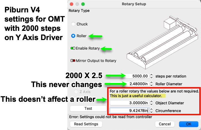
Very interesting info. I work for Lensdigital, the maker of the Piburn rotary. The pic I posted above are the correct settings for our product. I also own a Omtech 60W that is set to 2000 steps on the Microstep driver boards and the proof is in the pudding.

Default steps per rotation for an Piburn on an Omtech is 5000


according the the manual I downloaded from Piburn.

I admit to coveting one of those, but I haven’t come up with a project for it. One of these days … :grin:

And, yeah, the Y axis on my OMTech is set for 5000 step/rev. As always: trust, but verify.

Hi Ed, for the Piburn roller if your Y axis driver is set to 5000 SPR then your steps in Lightburn would be 5000 X 2.5 = 12500. :+1:

Not on my OMTech its not!

Definately 2000 Steps/Rev (as long as I don’t mess things up by hot plugging my axis - see above)

Note also that there are different model PiBurns. Some with chucks connected directly to the stepper, some with rubber drive belts, some with rollers.

Generally TWO things decide how many steps/rev on your rotary (ignoring belt drives and other types of “gearing”)…

  1. The steps per rev of the physical stepper used in your rotary. Most steppers are 200 steps/rev by default.

  2. The “MicroStepping” parameter set on your stepper driver. Most machines are set up to microstep for better resolution:

So, with the chuck on my PiBurn 4.0 (mounted directly on the stepper shaft) the Steps/Rev (Pulse/Rev) on the driver in my machine is set to 2000. Done. (You can also see the DM542T assumes a default single-stepping resolution of 200)

As far as your stepper is concerned, the only thing which really matters is what settings are applied at your driver.

Now if your rotary uses a drive belt of some sort that adds additional gearing. Also, if you are using a roller, then the diameter of the roller wheels also come into play.

THERE IS NO DEAFULT for PiBurn. PiBurn doesn’t control the steps/rev. Thats entirely up to the driver in your machine. My PiBurn single steps at 200/rev like almost all other steppers. IOW: The steps/rev of a single PiBurn can change depending on what machine it is hooked up to (and what the DRIVER microstep settings are).

1 Like

This topic was automatically closed 30 days after the last reply. New replies are no longer allowed.