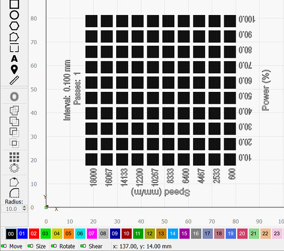
I have an RA2 Pro. I wanted to make a mug that has a material test on one side, and a clever saying about it on the other. My Rotary/Chuck os mounted horizontalyy (east to west. Is there a way to rotate the material test 90 degrees? I have tried several different option and cannot seen to find on that does that.
Can’t say I’ve ever attempted this… You could rotate your rotary and change the scan angle on your graphic…?
![]()
I was hoping to avoid that. Correct me if im wrong, but i would also have to change the axis i plug into, correct? I currently plug into my y axis, and would have to change it to Z, if i rotate the chuck, 90 degrees, correct?
No, just rotate the rotary and set scan 90 deg then Y axes will be moving…
Not as a permanent solution… this is a one off design? You generally don’t want the Y axes doing all the work…
As far as I know there isn’t a way to change it’s orientation… I also don’t remember anyone trying to do this, but it’s not a bad idea…
I know what my values are before material test came out, so I’ve never used it on a mug…
Would be a good addition for feature suggestions.
@Rick might have knowledge of this…
![]()
Thanks for that, but now i am thoroughly confused. The Y axis motor is what gets unplugged, and plugged into the rotary per my lasers (Longer ray5) instructions.
Let me think on it… I did this on my machine for a certain project, just need to remember how I did it…
Mines a dsp, but I swap the Y axes with the rotary, so I think it’s the same game.
Maybe we’ll hear from @Rick about how to handle this.
![]()
Seems way easier to make your own test grid. Only takes a few minutes. 10-11 layers (or 1, or 20, lol) plus power scale applied to individual rows or columns.
I have half a dozen I made myself now, and almost never use the built-in ones because of complications just like this. (Size, shape, location, odd increments, spacing, fonts, scanning method, etc.)
My machine speed plateaus at about 6k mm/min on the stock test because of the rapid direction changes. That also introduces wobble. Plus, my laser driver doesn’t play nice at low power and higher speed in that scenario. If I set it up my way, I can scan entire row just like an image and get more representative results.
In the Material test, click Save GCode and save the GCode somewhere convenient.
Exit the material test tool.
Click File, click Import GCode.
Rotate the Grouped Vector file 90 degrees as needed for your rotary tool.
Yes. The Engraver is free to engrave along the X-Axis (east-west), which moves the least mass, which is the fastest and least likely to slip.
The Y-Axis travel now wraps around the object on the rotary tool. It is often said as ‘Rotates around Y’ because the Gantry is now stopped somewhere on the unplugged Y axis and the rotary tool takes its place.
Good to know. I’ve never imported GCode but have often wondered if it produced an editable graphic.
This will not retain cut settings, though, which is somewhat important for the material test.
This is debatable. The shapes imported reflect the laser path and not the original shapes directly. Everything is imported as a single complex shape consisting of only line segments (not curves) and all shapes are open.
It can be useful to visualize the g-code, however.
I had to check… You’re absolutely right. (as usual) ![]()
If it doesn’t retain cut settings, is it only importing geometry and defaulting layer settings to C00? The cut settings would have to be contained in the GCode or it would be useless for program transport, so it’s rewriting them on import? That seems odd to me, but I’m definitely no coder!
It’s not importing geometry per se. It converts non-S0 G1 moves to lines in LightBurn.
Yes.
The g-code contains commands that have the outcome of the Cut Settings being interpreted to speeds and feeds. It’s not the Cut Settings themselves. The power and speed settings could possibly be retrofitted to Cut layers but all other layer information would not be retained and may not necessarily have the same layer assignments as the original.
Bottom line, g-code isn’t meant to be a storage format for design-time activity.
Thanks, PY. I think I understand. I certainly can’t knock the dev team for my poor understanding of the subject matter!
This is a very large boat, which most of us are in, you’re welcome to join us… ![]()
I don’t know if it’s really a poor understanding compared to just assuming it should work a certain way… bitten me a few times.
Now I’m not sure if you can rotate or not… sounds like not… Did I miss it somewhere?
![]()
I don’t think there’s any user accessible way to rotate the material test. I’d suggest building your own or using an externally generated test.
Thanks for the clarification…
I think you should mark the thread solved in your last post…
![]()
This topic was automatically closed 30 days after the last reply. New replies are no longer allowed.
