I have been through a few tutorials, but can’t seem to wrap my head around this subject.
Background:
I have been using CorelDraw and a ULS Versalaser for the past 9 years, making rubber stamps. I can do this in my sleep
Th cost to regas the Versalaser has become just too high in relation to the machine’s main purpose - rubber stamps.
So, I got a K40 derivative and this has been a mixed blessing. It does the job, but I have a very high failure rate on stamps with fine detail - the machines lack of PWM was becoming apparent. So after 8 months, I caved and ordered a Cohesion 3D board.
Up to now, despite a small learning curve(having to convert files from CDR to SVG), using K40Whisperer was really straight forward.
With the Cohesion board, I immediately had to upgrade from XP to Win10 for my laptop to register the machine. Be gentle with me here, I’ve been using the same XP powered laptop for 9 years…all it has had to do, is run the laser - I create the artwork in another room on a different PC.
My struggle with the new setup is multifaceted, importing SVG files into Lightburn presents me with an image I’m not familiar/comfortable with - i.e. not a classic negative.
Could someone please point me in the direction of exactly what steps to take after importing an SVG and having a file ready to send to the laser? Filling with black, leaving white space for text etc
The second issue, is that the laser doesn’t seem to respond correctly to my commands with respect to head positioning.
The machine has sensors that will guide the head to its home position - Top left.
I have told Lightburn, that the origin is top left - this is indicated by the double dot at the correct point.
The machine will home to this point…but when I click the ‘set laser position…’ icon and click on a spot near the home, the head moves to the bottom left. To test a file, I have had to position the artwork roughly in the middle of the workspace to prevent the head from flying off into space.
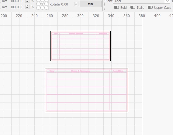
In Corel, I have the image setup as follows:
A frame 2mm larger than the actual stamp size.
A red cut line at the correct stamp size.
The stamp detail set 2mm in from cut line, so it won’t be affected by the flame.
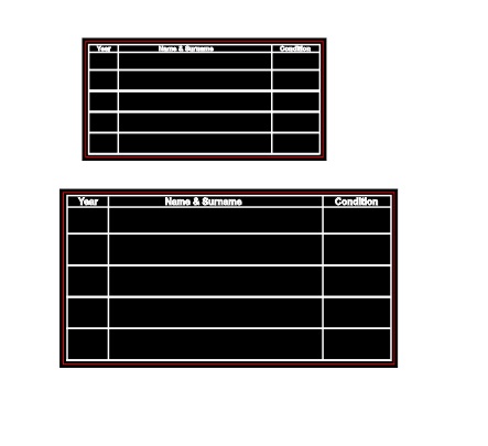
Black background and to engrave and white detail to remain.
The SVG file looks transparent when imported into Lightburn.
I have no idea what to do next.
On one guide I saw mention of creating a border and filling that - how do I create a border(does the imported file not already have a border?).
What I failed to mention with the laser setup, is that the images I have tried to engrave, are upside down…as if the whole bed has been rotated 180 degrees.
I can’t help with most of your issues as I’m very new to this laser malarkey. However, on your SVG transparency issue: Have you tried using “.ai” (Adobe Illustrator format) instead of SVG? There’s also a macro for Corel that comes with LightBurn that might make it a little easier (it uses .ai in the background). I’m not sure it will help but you might be worth trying it. If you could upload a sample .cdr and/or LightBurn that might also help us find a solution.
Thanks Marcus,
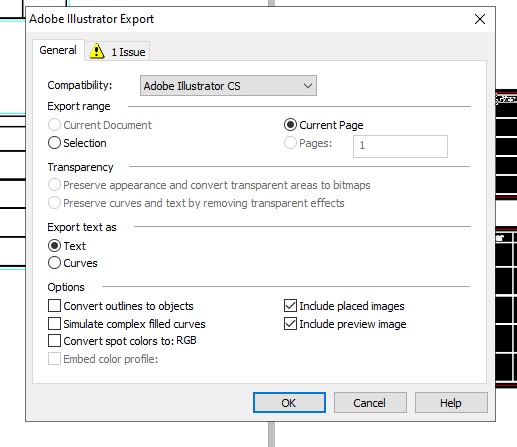
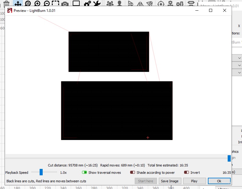
I have tried importing the file as AI - not sure which options to choose, so left it default.
The result looks the same as SVG - I have the preview below: However the text seems to be missing.
Thank you so much for all your effort Ralph!
I had gotten so behind with work as a result of the changeover to the Cohesion board, that I have temporarily reverted back to the old setup.
I will in any case try your tips on the stock board, as the output also differs from the ULS result.
For example, lines that are perfect at 0.5 on the ULS, I have to bump up to 1.5 for the Chinese laser and they still come out a tad too thin.
Hopefully I can catch up soon and give the new system a test by next week.