just spent 4 days trying to get my conversion to home and recognize the limit switches , results no go.
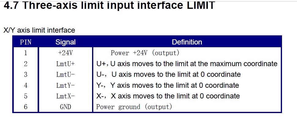
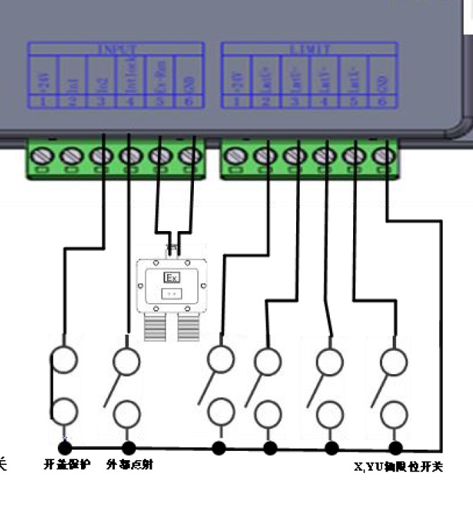
I have a simple 12x24 highly upgraded k40 which I built, I just switched over from smoothie board to the ruida 6432G . I have gone over every listing for this problem on this forum and tried everything to solve this problem. Mine is currently wired with the same mechanical limit switches one wire to the common pin and the other to the normally open pin on the switch, on the board the common wires for X and Y are run to the limit section #6 outlet which says power ground and the x and y to the x- and y- outlets #5 and 4. seams kind of odd as I naturally assume the ground is not powered ? and I see that the u axis has a + and - outlet, unlike the x and y. another odd thing is I see the wiring diagram shows the ground line looping around and going to the input #2 outlet on the input block ? I’m wondering if I need to run a ground from the limit ground to that input also ? anyway In vendor settings I have enable home checked for x and y ,I have the motors slowed down enough and I have tried every possible combination of dir polarity and limit polarity and when I use test on the panel and push the limit switches they both turn red , yet when I hit home and push the switches the motors do not stop they just keep going . I have upper left set as origin and head position. I have tried changing from absolute cordinates to orgin . and nothing. just seamsto overly complicated when it should be easy. I’m just a hobby guy not an electronics or computer guy. I have seen these exact same posts as mine tried their ideas but nothing. I did see one where they were talking about controllers that had x and y minus and plus connections mine only shows x and y minus connections ??? Starting to boggle my mind HELP
also when I start the machine it should go into a homing sequence, which it does not do even though both axis have it enabled . If i hit the home button it will try but crashes and limit and or homiong switches do nothing
You lost me here…
Don’t confuse the home and limit switches… they are not the same. Once a home operation is completed, the home switches are ignored. The limit switches are active.
The inputs to the Ruida are normally active low… meaning that the home switch for each axes will be wired, one side from ground, switching the input of the Ruida to a ground potential when activated for an active low at the controller.
This is pretty common, especially with metal machines that can be at ground, where you only need a single wire to sense the switch being activated.
These can be changed within the Ruida to be active high… if you have NC switches.
Where are you now? You stated you got it to home, but then seemed to indicate it wouldn’t home…
- when you power it up, does the heads move in the right direction to engage the home switches?
- Homing needs to be enabled in the Ruida for each axes.
Good luck… we’re here if you need help…
![]()
when i power it up it has never gone into a homing sequence, it only attempts to home if i hit the home button in the center of the jog buttons. WEhen itr was controled by the smoothie board it homed upper left and the limit (homing ) switches were wired as normally closed, but I changed the wireing to normally open as I read thats what ruida was looking for , But I feel it may be a defective unit as it has never auto homed .
and yes x and y both have homing box checked
and if you look at their explination pin 6 is a power ground output which is where I have the common wires from the homing switches wired to the NO pin on the homing switch I have wired to the y- and x- pins on the controller
It sounds like you have it wired up properly…
If you power it up, does the display show any kind of error message?
I think this is the Chinese → English translation… it’s just ground relative to power… so it’s a common connection…
What does the Ruida display on it’s leds when you activate the switch?
How about U/Z → diagnostics…?
Is the Ruida seeing the switch activation…?
You can check these with power on the Ruida.
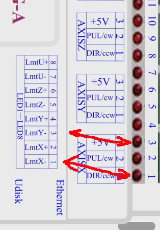
also via the control panel U/Z → diagnostics … this is my Y axes home switch active…
Make sense?
![]()
this control 6432G has no lights on the wireing terminals like yours it just has the u/z diagnostics and when I push on the homing switch it lights up so they are being seen. yesterday I did contact cloudray thru amazon and they sent me some instructions that may have me on the road to a solution ! one of the big problems I find is that their manual is more uninformative than informative ! I not being familiar with dsp controllers assumed ( and as Benny Hill always used to say when you assume you make an A_ _ out of You and ME) that I only needed to check the homing boxes in X and Y under vendor settings, which I did . There was no mention of going to the settings menu on the other side of RDWORKS and setting X and Y homing to yes. When I did that and powered up the machine it started the homing sequence for the first time, it did of course crash into the lower right corner and grind until I hit stop . So I’m moviving toward a solution, I sent them a reply and asked for a solution for getting it to home to the left rear ( rather than assuming I could fix it with changing limit polarity and dir polarity on my own) I will wait for thier responce and try it. I will come back and keep you informed as to my progress. Thanks for responding. once I get this correct I’ll probably be back for wiring advice for the air assist wiring .
If you have NO switches, you can’t invert the home switch inputs…
If, during home, it moves in the head in the right direction it should work…
On mine, you can press the key on the console to stop the machine if it goes astray… I suspect the same hold for yours. This prevents having to cut the power… and gives you control…
Keep us updated… sign out if you need help…
Good luck
![]()
ok, cloudray has fixed most of my problems ! I did’nt have auto homing set in the rd works user settings. I thought I only had to set x and y to home in vendor settings , then it would home but crash int right lower corner, next they told me to set x dir polarity to positive, and limit polarity to negative . set y to those same settings and they also said set z to those same settings. so now it homes and backs off properly. but now I can jog my z bed in the u axis on rdworks , but not the z axis in lightburn, so I need to figure out the z bed next , another message to cloudray and I’ll see what they tell me overnight
I don’t know RDWorks, but the Ruida won’t do much of anything until it does it’s home sequence…
It would be interesting to know what that changed…
Good luck
![]()
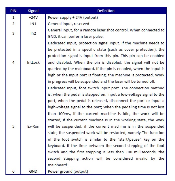
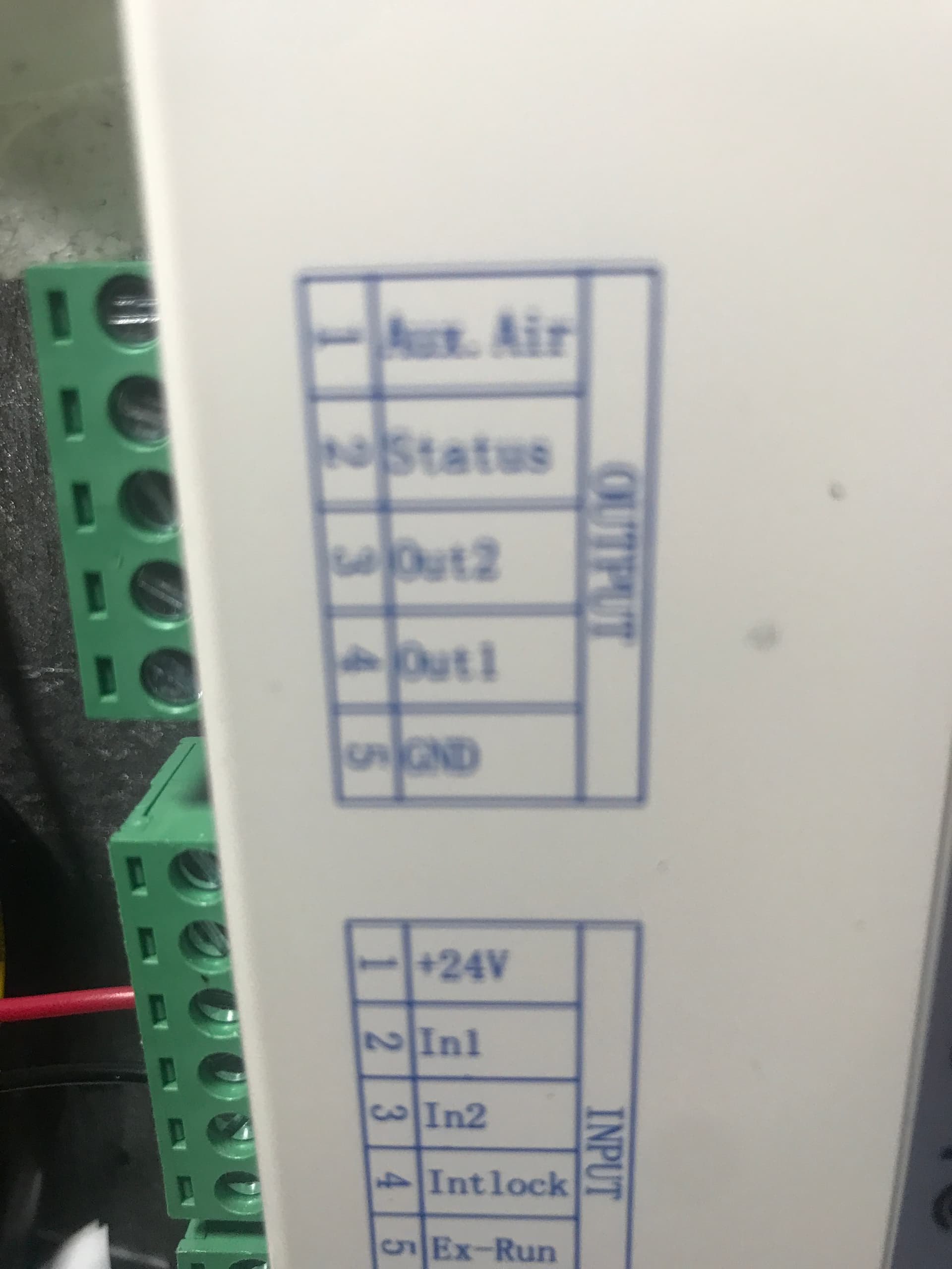
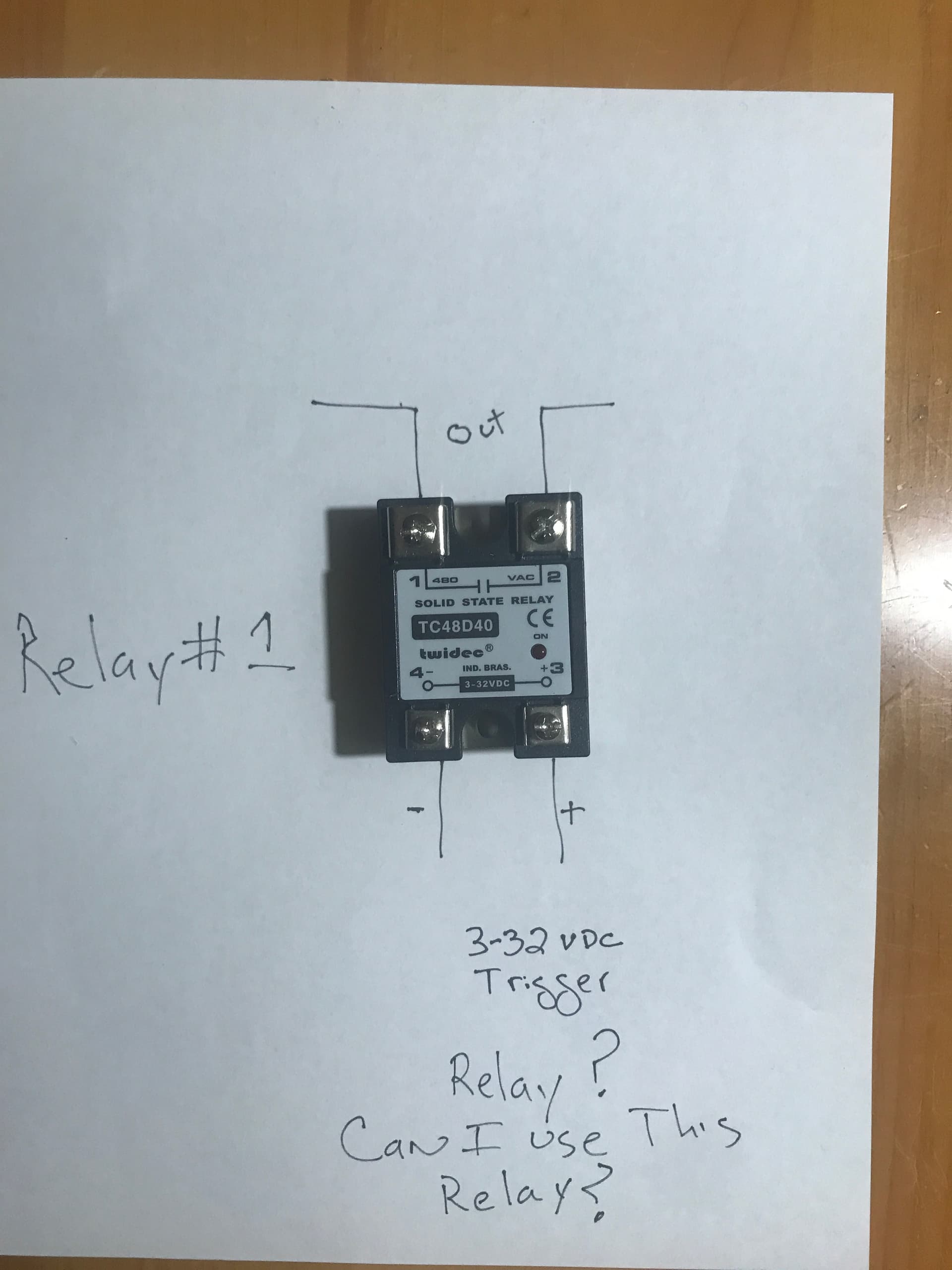
jake , I found an air assist post where you have your simple ss relay set up to kick in the relay, that was the same way I hd mine set up on my smoothie board, but I cant figure out how to wire it on the ruida 6432G their wiring diagram is to confusung to me . I will upload a photo of where they connect and thei wiring diagram. they are pulling the 24v from the input 24v to the controller to use to power the solenoid I’m just unsue which two wires to run to the trigger on the ssrelay I have basiclly the same one as you
any info would be greatly appreciated, Thanks
I meant Jack sorry
If you want status, then just run 24V to the + side of the ssr and the - side to the Ruida Status sink.
I believe the aux air is the same as wind on mine.
If the machine is in run mode, then status goes active (sinks), while it’s running a layer with Air Assist selected, then Aux Air should go active or sink current…
Make sense?
:
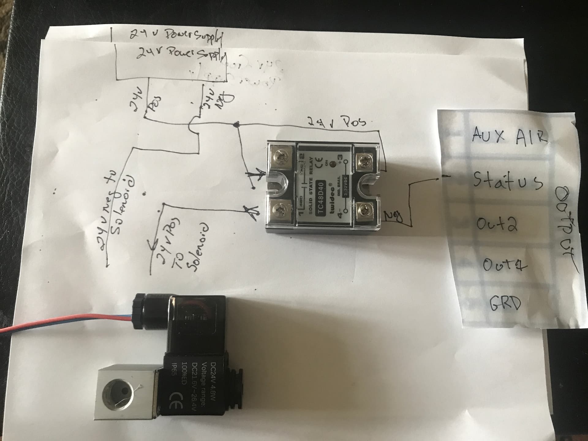
I got my wiring out of the Ruida manual, just like this… so yes… they should know…
I have made an assumption that Aux Air is air assist or wind, but status should be status…
![]()
thanks much i’ll give it a go
You should be able to use a voltmeter to check these sinks if you don’t trust’em.
Good luck
![]()
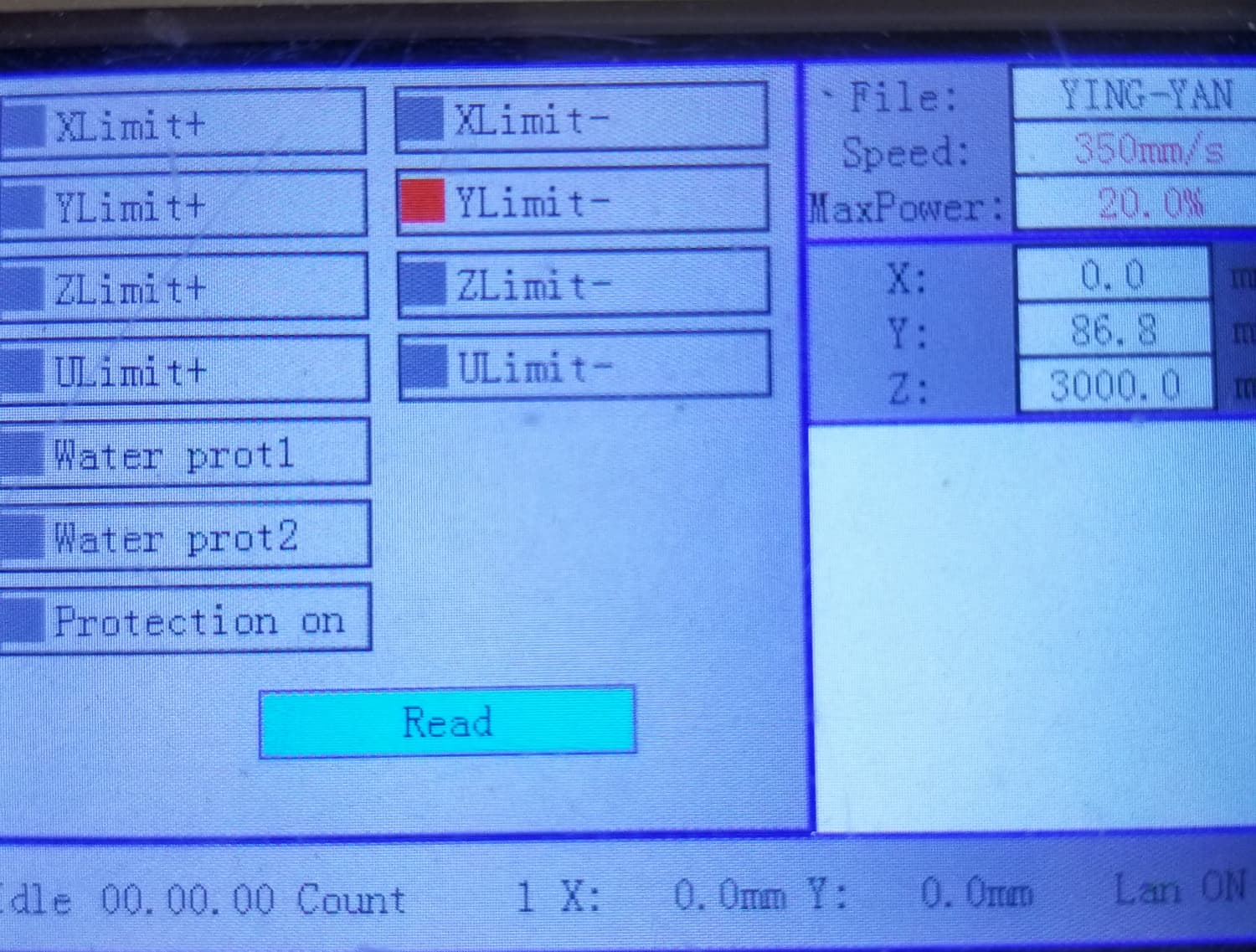
OK, finally got all this sorted out and for any one with a cloudray 6432G Ruida controller. Here is what works for getting your machine homing properly and hooking up your air assist ! Now this is only for this controller and my machine which is a highly modified k40 now a 12x24 cut area which homes upper left corner. Also I’m using Rdworks to make the changes. Here goes for homing: so go to vendor settings and click read ,in x axis set dir polarity to positive, set limiter polarity to negative. then check the box enable homing, now go to y axis and set them the same as the x axis . then click write. On mine I then click reset on my controller. Next in rdworks over on the right side and click on user then select auxillary, then under home parameter change the x and y auto home boxes to yes. from now on when you turn on your machine it will auto home. you may have to reverse your jogging in lightburn or rdworks .
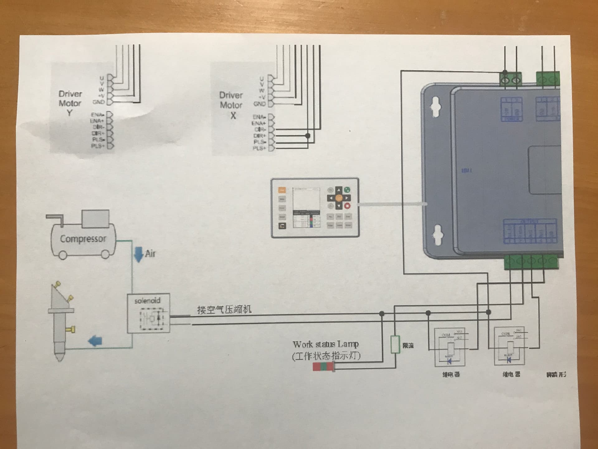
Next up is hooking up the air assist: see photo attached,
I HAVE SPENT MANY HOURS TRYING TO SORT THIS OUT:
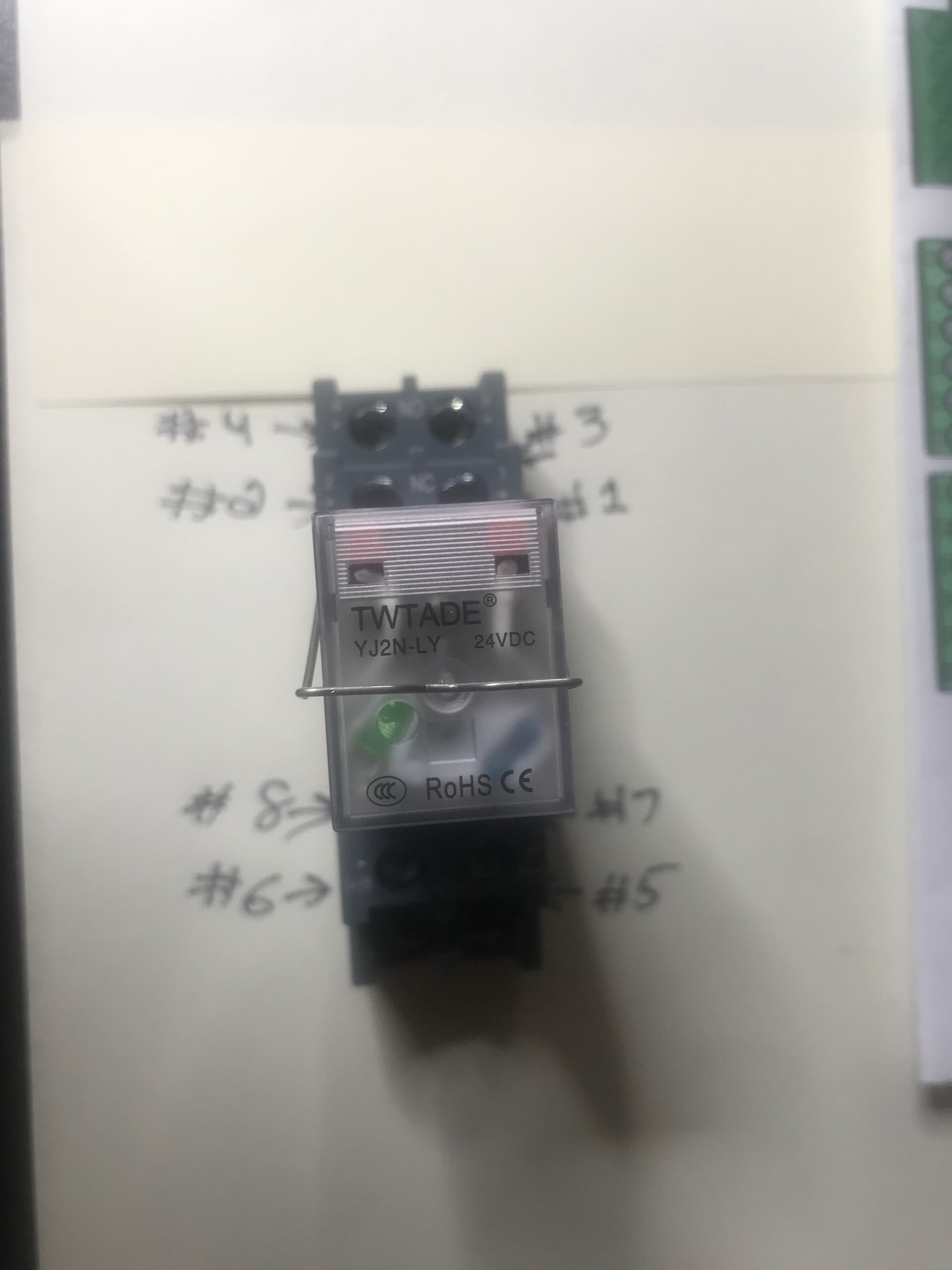
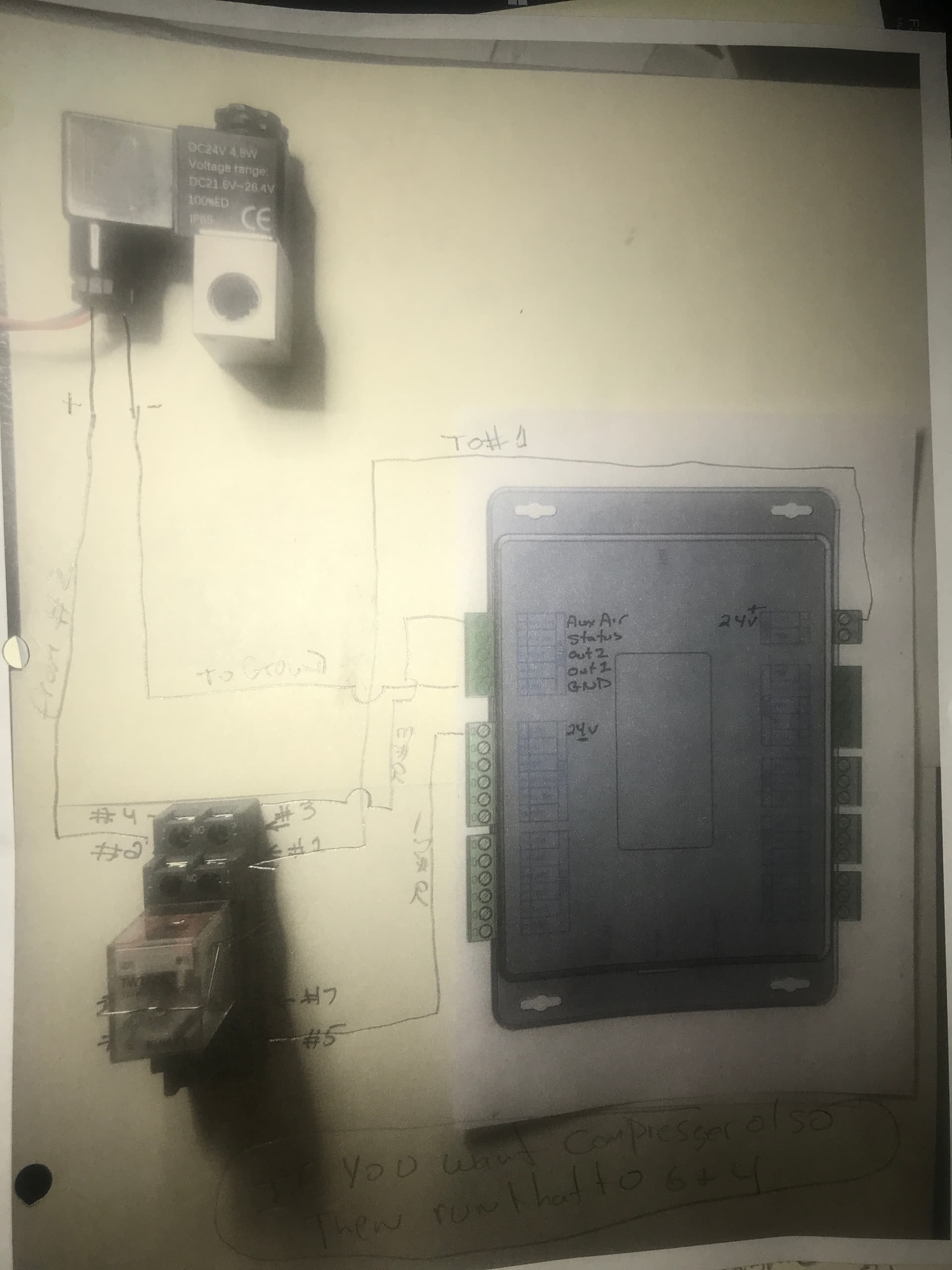
this is only for my 6432G controller, you will need a TWTADE/dc 24v, 10a relay, I’m also using a Tailonz pneumatic 24 volt n/c solenoid (#2vo25-o8) it has the resistor already installed. Now the solenoid does have a pos and neg side and it does matter how its hooked up. In the attached photo diagram , You run a 24v positive line from same connection where you run the controller power in,your run that 24v positive line to the # 1 terminal on the relay, you run a line from terminal #2 to the positive side of the solenoid valve, then run a line from the negative side of solenoid to the #5 output ground terminal , then you run a line from the #1 aux air terminal on controller to the #3 terminal on the relay, then you run a line from the input # 1 24v+ input terminal and your done . Then you can turn on the machine on the control panel click menu, then scroll over to function set, hit enter, scroll down to diagnosis, hit enter, then scroll to aux air until it is highlighted and when you click enter you shold see a green light in relay and a green light on the solenoid. If yo do then you have it wired correctly and when you check the air assist box in a layer on lightburn your air will come on. I have mine set up so the compressor always comes on when machine is powered up, I just use the relay for the solenoid and I have a gas flow meter which I adjust for either cutting or engraving. ( hope this helps you out) I tried many suggestions from many posts and none of them worked, so I finally figured it out myself !