Hi all,
I am trying to make AirAssist on my CO2 laser but there is an issue.
I have 80W laser with RUIDA - RDC 6442G-B, mainboard version RDLC-V8.00.67 and 24V DC 18W solenoid.
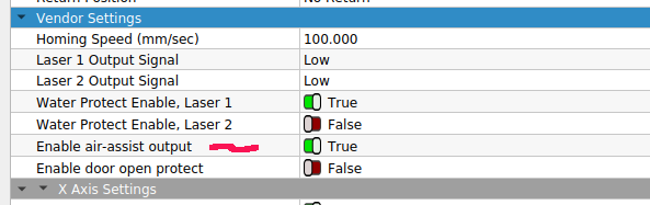
I connected Solenoid to pins +24 and Wind and there is no effect. If hit Start in LightBurn nothing happens. AirAssist is on. Tried RDWorks but the Blow Type option is not showing.
Tried change polarity, try STATUS pin - no effect.
Can you help me how to fix my issue for proper working?
A bad solenoid, a wiring error and a bad controller are remaining possibilities.
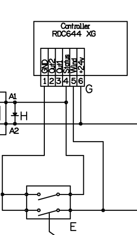
If you have a volt meter or a small 24V test light ( or a couple of 12 volt test lights in series ) - with the solenoid disconnected - confirm the action of the controller between Wind and +24V. Also prove that the +24V is working compared to ground.
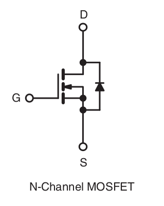
Using a meter (with the solenoid disconnected) measure the number of Ohms of the solenoid wiring in both directions. The solenoid in the Ruida manual on page 10 shows a Back-EMF diode to trap the spike from the collapsing magnetic field when the solenoid deactivates. If you connect it backwards it will behave like a short circuit and not operate.
You can just ground the wire going to the controller from the solenoid and the solenoid should ‘pick’. This should simulate the operation of the Ruida, by completing the path to ground.
I wouldn’t ground the ‘Wind’ pin, I’d removing the wire and physically ground it. I don’t think it would hurt the device grounding the pin, since it just goes to ground when active.
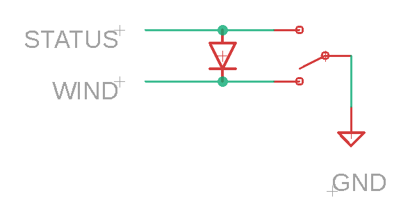
The other option, for testing, is the ‘status’ output, which is ‘active’ anytime the machine is in ‘run’ mode. You could move it there and ensure it’s operating correctly with ‘status’.
That should confirm or eliminate the controller. If it is the controller, I don’t know what other settings, if any, change the ‘Wind’ operation.
If they were backwards then the controller would get full 24v with only the diode/24v supply to limit the current. It would fail to ‘pick’ since the current would go through the diode rather than the coil of the solenoid. The solenoid wouldn’t get a voltage over 0.6v (diode threshold)…
I actually don’t have diodes in mine. Last couple of decades, mosfets usually have a reverse diode manufactured within them. The Ruida manual advises the use of EMF diodes, but I’ve run a long time without them.
I have seen solenoids where the reverse diode is molded within the coil body. These are usually marked with red/black wires to identify the orientation of the diode.
I’ve built a number of drivers and all the devices I use have this type of configuration.
Doesn’t mean I can’t be burnt in the future…
Dreamer…
If you wire the Ruida ‘Wind’ pin to 24v, it will ‘sizzle’ the mosfet in the controller when it becomes active, assuming the supply will produce the current…
There is a ‘stated’ limit of 500mA in one manual, and of 300mA in others. So if you exceed stated limits…
Most supplies go to their limit. It’s only job here is to supply you 24v. There is current limiting on most of these supplies to some extent, but how would the supply know if it was burning up your mosfet in the controller or you were moving one of the motors…
This kind of rang a bell and I used this for a while to manually enable low and high pressure. I saw the way they used a double pole switch on the solenoids in the advanced air assist package… for manual override of air.
Got lazy and did it this way… there is a ‘center’ off for ‘auto’… Up is low pressure in my configuration. This was a while back…
So there is no doubt that you can just pull the pin low…
If I connect solenoid to Wind or Status - no effect even if I enable AirAssist in Lightburn (in machine setting and parameter settings). If I connect solenoid to the +24 and GND when switch the laser on it “pick” and red diode lit - it show that the solenoid works good.
I made some measurement:
+24 & Wind connected without solenoid - result DC 23.99V
+24 & Wind connected with solenoid - result DC 1,422V
+24 & GND connected with solenoid - result DC 23,65V - soneloid works
Measure solenoid ohms - 35,5Ω
Are you certain that you connected the +24V to exactly the same terminal at the solenoid for each test? This result seems to suggests otherwise - be careful not to cook your circuits - this is why @JohnJohn suggested you use a 24V test light which offers some protective resistance.
The measurements would indicate that it’s trying to go low with a 1.4v when Wind goes active. This, to me would indicate it’s trying to go low, not making it.
I assume you are measuring from ground?
I measured my machine, ground to Status 24v, went to 0.4v when active.
@OffSign.cz is your solenoid a standard 24v model?
Does it have voltage & current rating on it…?
Any chance it’s a 36v solenoid…
I’m grasping at straws here… I hate to say it’s a controller, especially from your measurements indicating it’s trying to work…
Again, it doesn’t look like it’s really going to ‘ground’.
Doubt it and hope not. The only way this could happen is if the solenoid actually draws 676mA at 24v. There is a 500mA limit in one of the Ruida manuals, but another Ruida manual states 300mA…? Mine run around 200mA, just under.
It’s easy to check with the multi-meter if it’s isn’t on the solenoids placard.
Put the meter in line with the ground (or power) leads and do a mA check. Make sure you configure your meter for mA range/polarity.