RF mod validated. It offers the possibility to fine tune diode laser. You can gently adjust the power as your wish Thank you a lot for your help. I ll now try to get the best adjustment in Lightburn. Every advice is really welcome.
Won t it be cool to make a sort of tutorial in order to show how wire ruida with diode laser and co2 and Lightburn parameter to help other.
I m ready to start it and feed it with my experiences and some of other for sure.
Always 4.90 with sometimes values between 4.32 to 4.50 from time to times but at 10% I should be about 0.49v so my question is why manual % is OK and Lightburn “automatic” is not ?
When I plug my multimeter it shows me 4.90v so 100% in any case of material test.
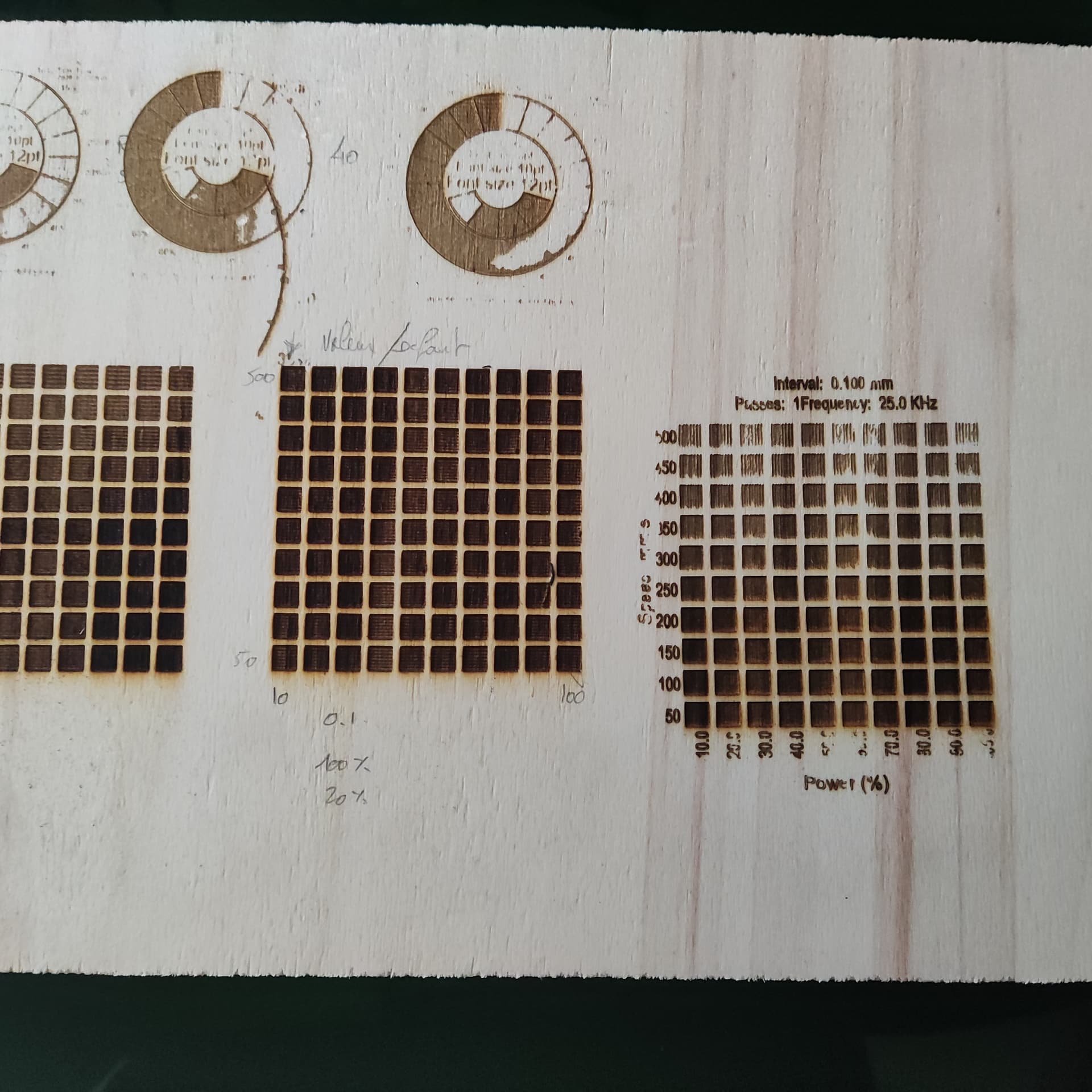
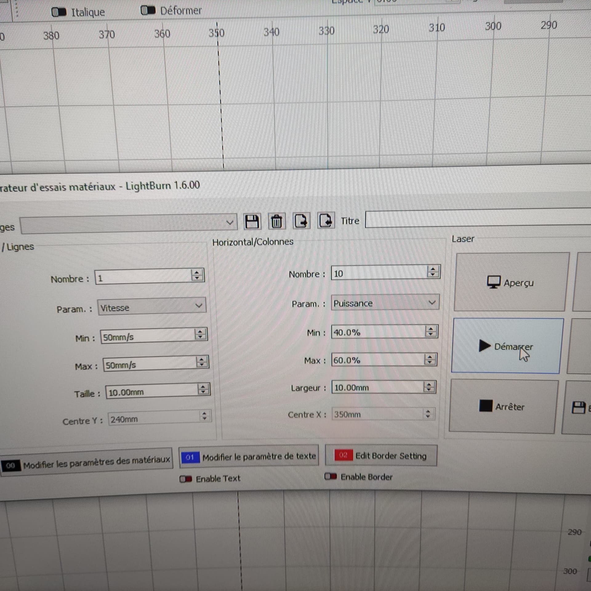
I did a test with littles squares with a color for each one and edit properties of color with a step of 2% each times and in this case it runs correctly not only in the results but in mesurements in multimeter.
So now I wonder how to really do a grayscale ??? I was told that diodes were the best but here…
I understand … I probably neglected some information, as I’m thinking rf mode…
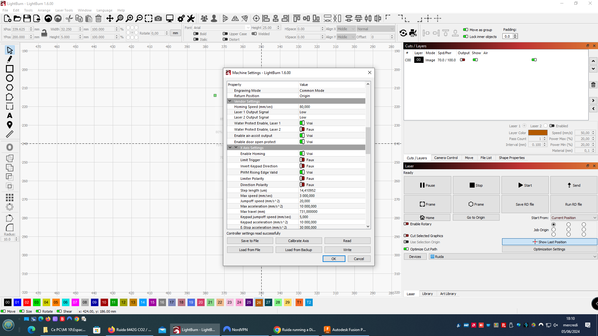
Glass tube mode - Analog mode
A tube will draw as much current as the lps will allow, so controlling the amount of current controls the watts out.
The standard lps works this way. The pwm or an analog dc control voltage → IN of the lps.. this controls the current limiting within the lps. This is how an analog device, the tube, has it’s current controlled.
The other control is from L-On → L or laser enable. When this goes low, it will lase at the IN specified current maximum.
This requires two signals, both pwm and laser enable.
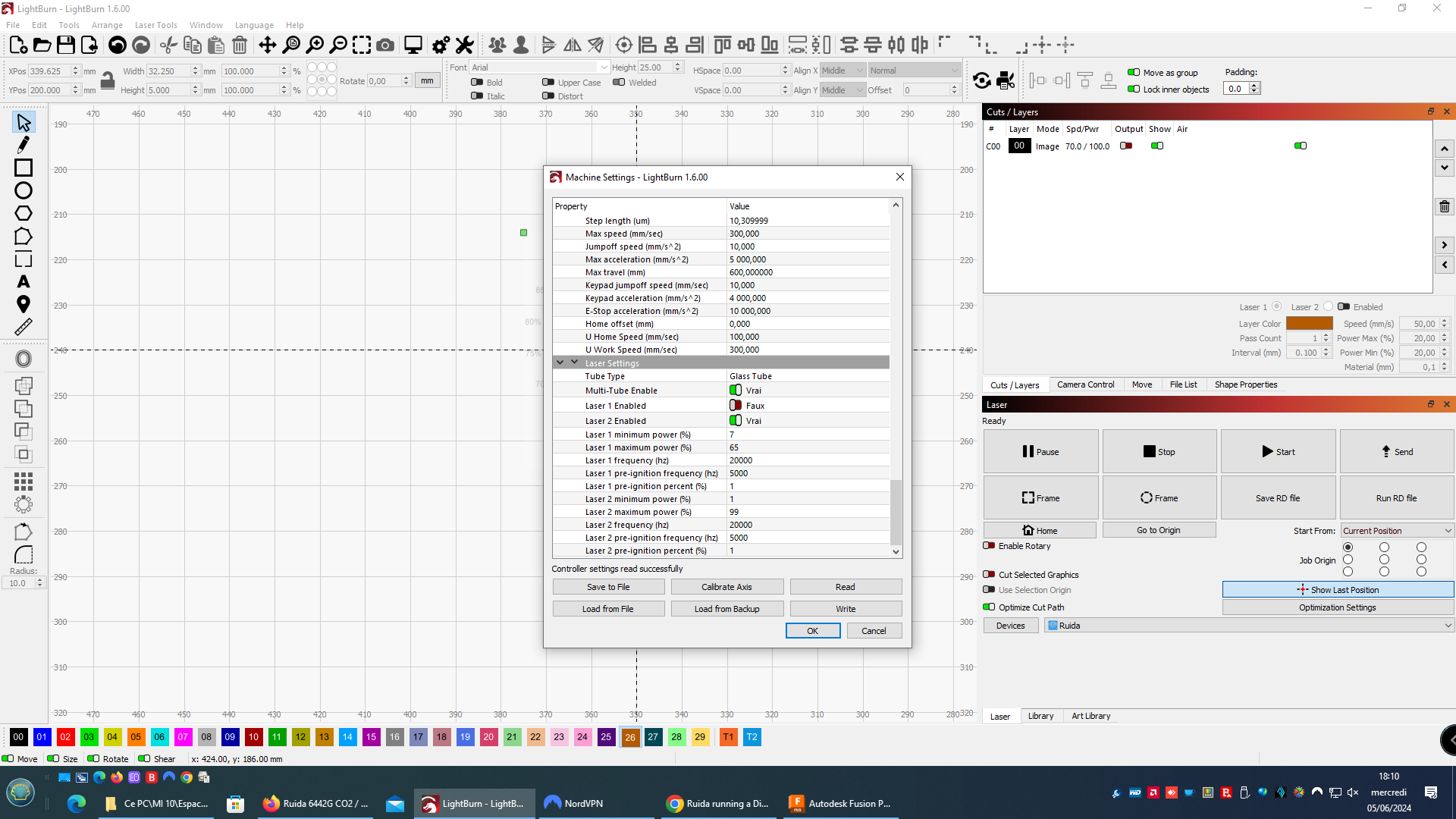
Metal tube - Digital
The issue is that in metal tube or rf only generates a pwm when the laser needs to lase. As far as I know rf excited machine operate in a digital mode, which is how the ssl module operates.
When I used mine in glass tube mode, the L-On1 output was used to gate the pwm to the laser module… I would not expect it to work properly in glass tube mode driving an ssl module.
I don’t understand anything… Do you have any photos of your job ? It could help… I m lost LPS is Laser Power Supply that s it ? I don t understand why I should plug my laser diode into the LPS…
Sorry not meant to confuse. We use lps (laser power supply) in order to distinguish it from a regular lower voltage power supply.
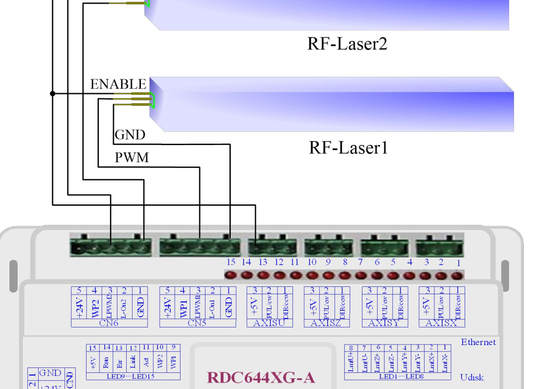
The IN terminal of the LPS is or usually wired to the L-PWMx (x is 1 for laser one, 2 for laser2) output of the controller. This is what needs to go to the diode pwm pin… I picked mine off the lps, since it was closer and the lps is turned off at it’s mains. I also don’t have to change connectors for one pin, just the way I wired it… same same.
If L-Anx is used wired to the lps IN terminal, I think you can ignore it. You must use LPWMx to drive the diode.
You hook it up like an RF module, except there is no enable line. Only ground and pwm, you must have power to the led module, but I’d suggest you get it from one of the supplies, not from the Ruida…
I think you have it… It’s not a complicated setup. I think the Ruida uses RF mode as it’s digital mode since an RF machines are digital.
I’m clueless about the wire color, so that’s up to you, there is no standard. I’ve seen red wires to ground…
I’d suggest you use the RF no pre-ignition option. For all I can make out with these RF modules, they operate digitally as that’s the only control to them… so I am not a wizard on what these options actually do.
I doubt with a co2 I’d seen any difference in only a few percent power change… so I’m not sure what you’re looking for.
If you have an image, you can use grayscale dither to change the power as it runs… creates lots of data to do this, but most of us have done it at one time or the other…
I don’t know of anything parametric that is used in Lightburn, if I’m following you here…
Keep in mind your grayscale will be compressed depending on the material/laser combination… You are likely to end up with a relatively small bandwidth from black to white…