Is there any idea when lightburn will fix the issue with the ruida controllers and the max power settings. I have determined that 55% on my laser is the max mA to run. I set that in the Ruida Controller. I was hoping that would then allow you from 0-100% of that 55% max but if doesn’t. Anything over 55% in lightburn is the same. So you have a real small window for laser adjustments. If your laser fires at 10% and max is 55%, you only have that 45% to use. Also it makes doing a material test file useless and you have to do all sorts of adjustments to get it to work. But the number percents don’t help you because lightburn doesn’t use the 0-100%. Thoughts?
1 Like
I think you’re looking at it wrong.
Your machine should have had the tube and PSU dialled in. You should adjust your power supply to deliver the maximum mA you want at 100% power.
Then you don’t need to use software to do the hardware’s job.
For example, the PSU in my machine can deliver over 50mA, but my tube safe long-term limit is 28mA. The PSU has an adjustment pot to limit the upper output, which you can adjust with a screwdriver to limit the output to 28mA, then you can confidently go to 100% without exceeding the tube limit.
1 Like
Where is the POT located at? I have a ZYE MYJG60W-Y-1, which I can’t see to find that exact model. Mine has the LCD built into. Is the POT screw inside somewhere?
Nevermind, I found the hole in the side, trying to adjust it lower now as I turn up max power on the controller also.
2 Likes
I don’t have my laser yet but have a 50w and Ruida controller coming and I was wondering the exact same thing as you. Were you able to adjust your PSU to max out at your chosen mA limit?
I was on my 60watt. Was a little tricky but it worked just fine. Now I can us 0-100% in lightburn.
1 Like
Just to clarify, when I use my K40 laser that has a Cohesion 3D controller, when I set the laser to 35%, that generates the max MA current that is safe for long term use. The digital displays on these K40s are notoriously inaccurate so I added a MA meter to be safe. When When I set lightburn to use 50% power, that represents 50% of the 35% I set the laser power to. I’ve verified that’s how it works with a lot of testing.
I just purchased a 50 Watt laser that uses the latest Ruida controller. If I’m reading this correctly, it sounds like its not the same for the Ruida. If I set my 50W laser to 50% max power through the keypad on the laser, and then set the max power in lightburn to 50%, does that 50% represent half of the max power set on the Ruida controller manually or does lightburn override that and does it become the master power controller? I will be adding a MA meter soon but in the meantime, if you know the answer, please share 
… it has no effect whatsoever on the power output from the software, and controls only the power used when pulsing, or running cuts at “default” power (which LightBurn doesn’t do, but RDWorks does).
On Ruida controllers, you need to set the power level output cap in the machine settings, which acts as a cap/limiter, or by tuning the power supply, which works more like the analog knob on the K40 / C3D combo.
Thank you very much for the answer. That explains why on my first engraving with the 50W laser that the engraving was much deeper than I expected. Now I know what I need to do
@mvansomeren The best thing to do is to look to see if you can turn down your power supply. My 60watt had a small hole in the side to turn a pot. I set the machine setting to MAX power and turn the pot down so when you use MAX your in safe range. Then you can use lightburn at any percent from 0-100. The is the best way in my opinion. Best way to get the most range out of the laser and then you can also run test material templates (they are tricky with the ruida and lightburn also). So then you can repeat results.
1 Like
Thank you for the suggestion. How do you know when you have adjusted the power supply correctly? Do you use a MA meter? Maybe you can put together a video on how to adjust the power supply?
Does your power supply have a digital display on it? I am thinking it does not, so if that is the case then yes you would need a mA gauge which you should have anyway. Make you you have the correct gauge as there are different gauges that say mA, for example, MA, is different the mA and there is micro amps as well. Need to find out what power supply you have and see if there is an adjustment POT on it to adjust output.
My Ruida display does show Max Power setting on the main screen. But nothing that shows milliamps. Right now it shows a power setting of 50% Max. I have the correct mA meter - the same type I used for my K40. I’ll have to look at the PSU later but I do know it is a 60 Watt power supply.
Right by default the Ruida board is set to 50% max. It won’t show mA anywhere on there. You need either a mA like the k40 one or a power supply that has the LCD display on it. If your PSU as a POT screw then you change the max setting on the Ruida in the manufactures settings to 100%, go back to the main screen and slowly turn down the PSU so when you git the pulse at 100% power it pulls your MAX mA for your tube. Start low and work your way up. Hope that makes sense.
It does, thank you.
Thank you.
You can use a digital multimeter on the ground side of your tube. It doesn’t have to be fancy, but if you have access to a True RMS meter, that’s a bonus. I’ve done this job with a $5 gas-station meter ![]()
If your PSU has a test button, use that - it fires independent of your controller at 100%
The hole where you will find the potentiometer to adjust output is usually down the long side, at about where you would expect the PSU’s PCB to sit. It can be on either side, depending on manufacturer.
Connect up your multimeter and press the test button, if you have one, if not, create a job that fires at 50% at 1mm/sec for 0.1mm, or any combination that gets you a 0.1 second burn, and send that. Check the reading. For argument’s sake, let’s say it read 12mA. Adjust the pot - anti-clockwise is normally ‘down’, but check. You only need to move a small amount.
Test/run your job again and read the output. If it’s higher, you went the wrong way.
Repeat until you hit ~5mA, then adjust your job to 80% power and repeat.
I do it this way to prevent damaging the tube. 80% ‘should’ be low enough that you aren’t overdriving your tube, but if you are, the time and power will probably be too small to have a damaging effect.
If, at 80%, it is still within your margin of tube power, run the job at 90, then 100% - if it is still within the margin, you can then turn up the pot at the PSU until you reach your desired level. If not, keep adjusting the pot down until you reach the level you want.
Personally, on tubes of ~100-150W, I like a couple of milliamps margin lower than the peak output. For under 100W, just one milliamp. This allows me to go to 100%, should I wish, knowing that there is no chance of damaging the tube. But, I’m a commercial cutter that runs 99% of my work at 85%. I would only go to 100% if I had a LOT of engraving, say, and that could get my time down significantly. Currently I have, today, about 260 500mm-wide signs to engrave, which I’m running at 300mm/s and 85%. pushing that to 100% would knock off a couple of hours, but I use the in-between engraving time to finish the piece. As it is, it finishes just as I am nearly finished stacking the finished piece, so if it was faster, it would be sitting, waiting ![]()
Every job is different, you will work out what works for you.
If you are unsure about the above, you can turn the PSU down as far as it will go and work up, but for me, that is over-cautious.
There are a number of benefits to going through this calibration:
- You preserve your tube from accidental overdriving - it makes it hard to make a costly mistake.
- You get to use all of the 1024 PWM steps available - where, by managing it in software, you lose all of the steps above your soft limit.
- You can be confident that what you set on the job is what you are getting, without having to calculate - 90% gets you 90% of what you have available.
- It reduces wear and tear on both the PSU and the tube.
I very, very rarely even look at my mA dial on the machine.
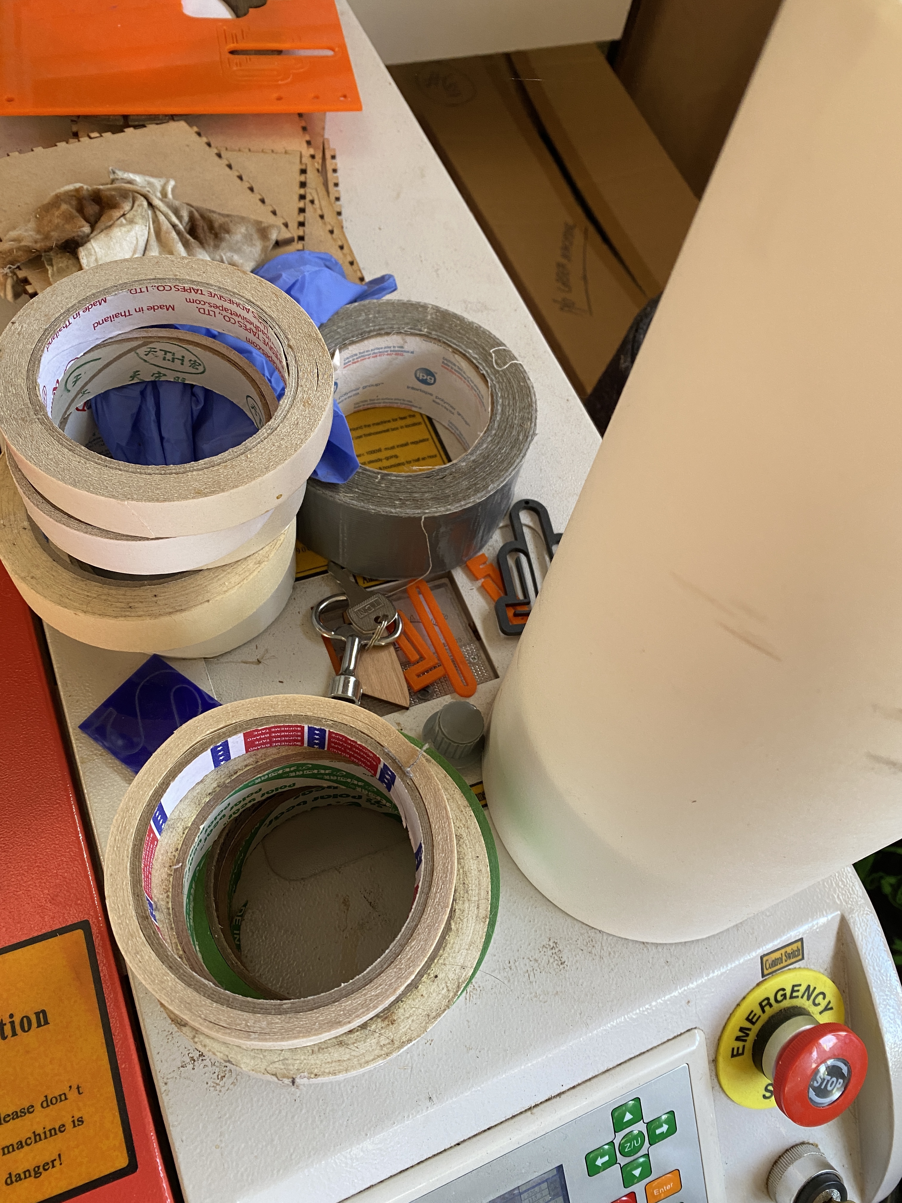
Here, you can just make it out, under the key and the ‘F*ck 2020’ offcuts ![]()
The reason is that I just don’t need it. I’ve made more errors by accidentally or forgetting I set the dial than by sending a job at the wrong power.
Thank you for the detailed explanation. I actually installed an inline mA meter today. It just sits on top of the laser in a 3D resin printed box. I think I’ve got it dialed in pretty good now. I did a quick acrylic engraving job to test it and it was at the depth I expected when I set the percentage in Lightburn.

Acrylic blocks are great for dialling-in. I have clear 20x20x20 blocks I use for checking power, especially on corners to dial in upper/lower power.