Hi friends. I have a 130W CO2 machine with the Ruida RDC6445S(EC) controller. I am trying to install the air assist but the status and wind port are always on (24V). Even if the machine is not running, the status is 24V. The controller is configured with the “Enable Blower”. Can you help me? Best. Caio from Brazil!
The Ruida is an active ‘sink’, so you should connect one end of the ‘relay’ to 24V and the other to the Ruida.
Status should go low when you press ‘start’ and ‘Wind’ goes low when the layer with air assist enabled is executed…
Where is this setting?
![]()
If I connect the the voltmeter on the 24V+ power suplly and on the status, the voltage is always 11V. Is this correct?
I am using RDWorks, and the “enable blower” is on the machine settings.
Tks.
This is a Lightburn forum and I have never run RDWorks, so I don’t know what the ‘enable blower’ does, maybe the same as Lightburn. This is the controller you are changing?
How do you have the solenoid connected… 24V to the solenoid, then to the Ruida?
‘Status’ should go low when you press ‘start’ on the machine console.
![]()
The status and wind connections are the ground, not the positive. This lets you choose +24 or +5 for your relay. Status will go low on job start, wind will go low on command from the controller depending on your air assist settings.
The Status and Wind are normal 400mA, with a max of 500mA. If your solenoids pull more than that, you will need the relay. Also, with direct connection of the solenoid you will need a blocking diode on the solenoid, not sure about the relay as I have direct connect.
The diode is for an induced reverse current. Anything with a coil does this when the field collapses.
If you need it for a solenoid, you need it for a relay (coil)…
![]()
I figured there was a reason, just didn’t know what. Good to know it applies to both solenoid and relay coils.
All transformers (coils) work this way. This is a radio circuit but it’s a transformer, higher frequency, but the signals work the same. Notice the output is ‘inverted’ to the input.
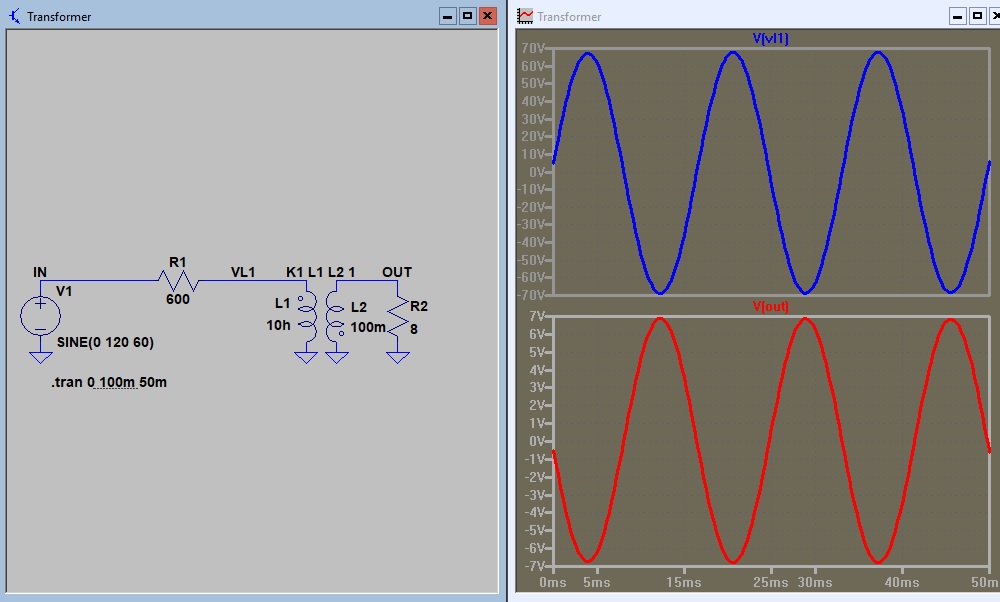
If you build the field up, such as energizing the coil for air, you are doing the 1/2 of a 1/2 wave (1/4 wave), in the graphic. So it’s building up in one direction and when the field collapses, the coil now acts as a ‘secondary’ so to speak and produces the inverted or negative output…
Make sense?
![]()