Hey everyone, need some help from the Ruida electrical gurus please.
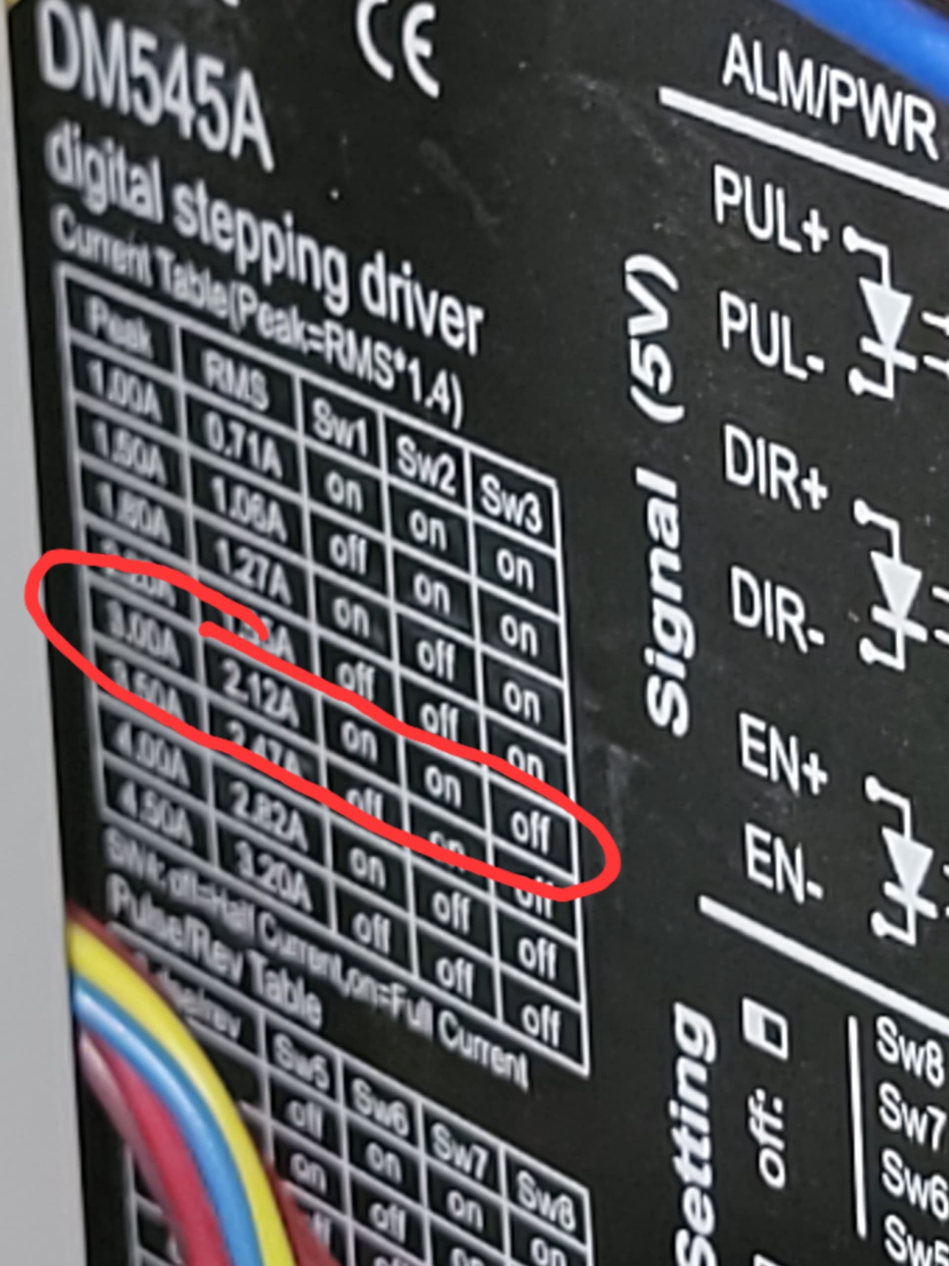
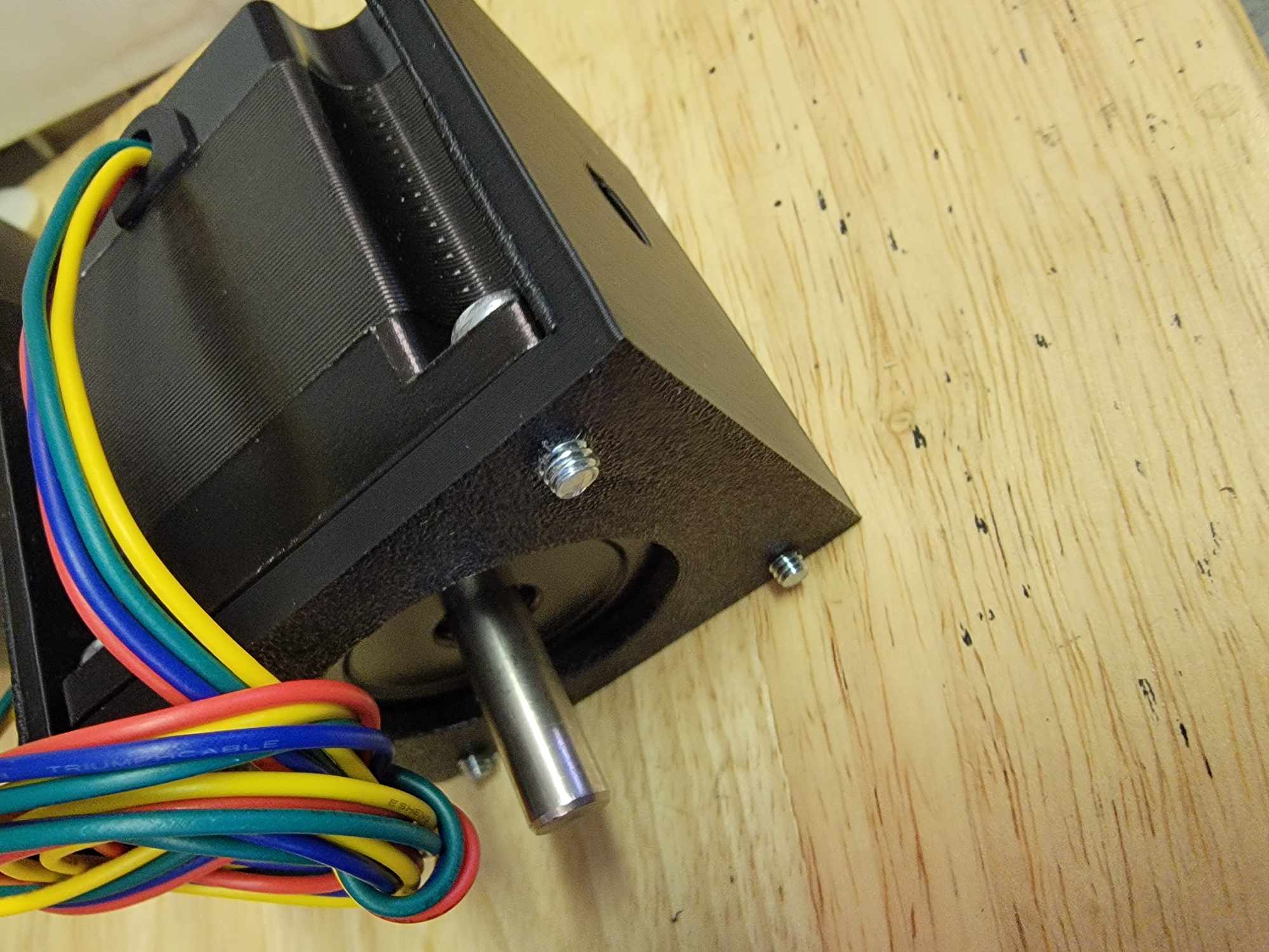
Put together a rotary using a Creality Rotary Pro, a couple 3D printed parts, and a NEMA 23 motor. (Pic of motor specs attached) Thought I had it figured out since I’ve been using it for a while but tonight noticed some connection wires smokin’. The motor itself wasn’t abnormally warm or hot to the touch.
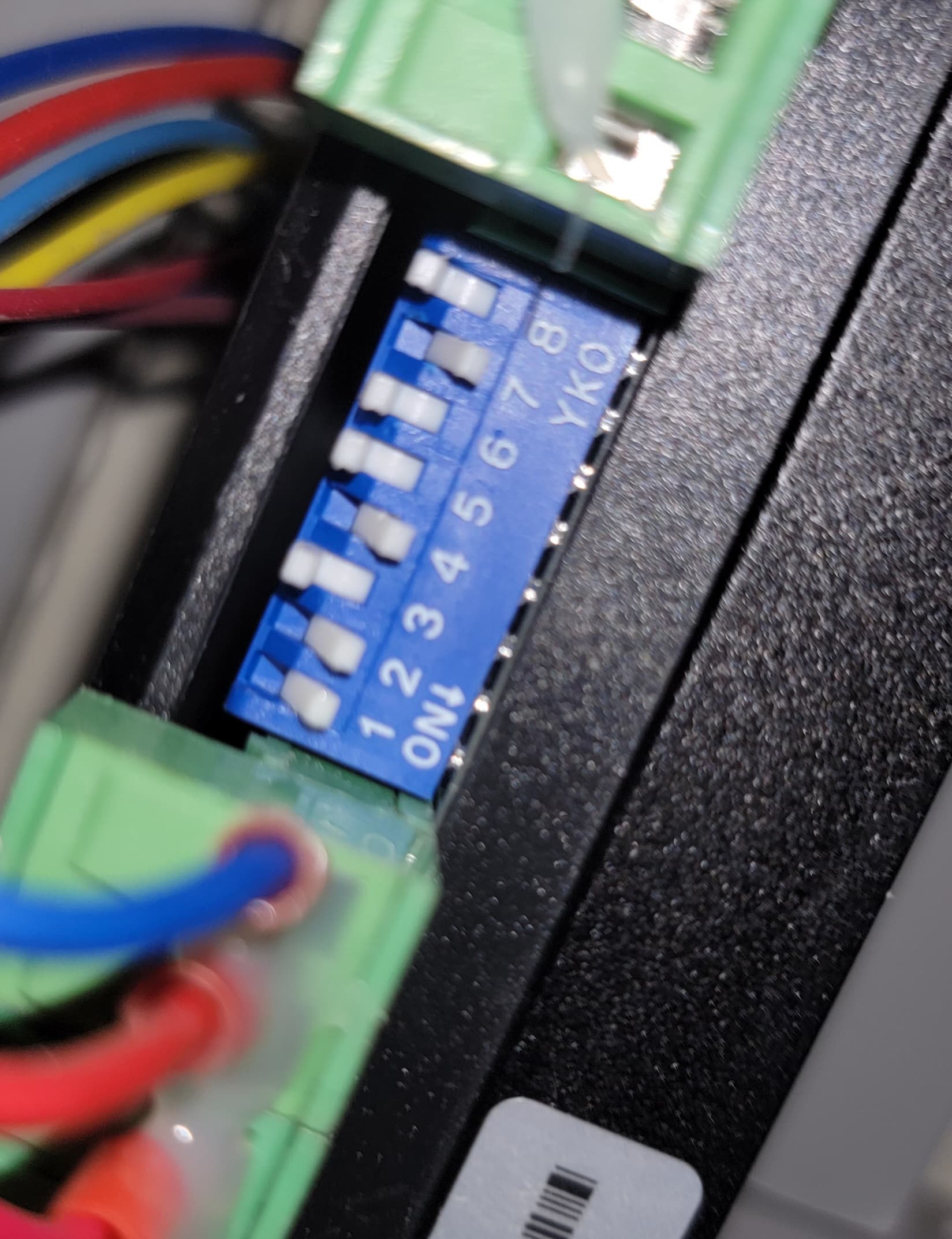
This is a Monport 100w CO2 running the KT332N /DM545A controller. Attached are pics of the dipswitch settings which should be set correctly, or so I thought. Default config for y axis for laser is as pictured except switch 1 is set to off.
That suggests the wire or the connectors are too small for the motor current.
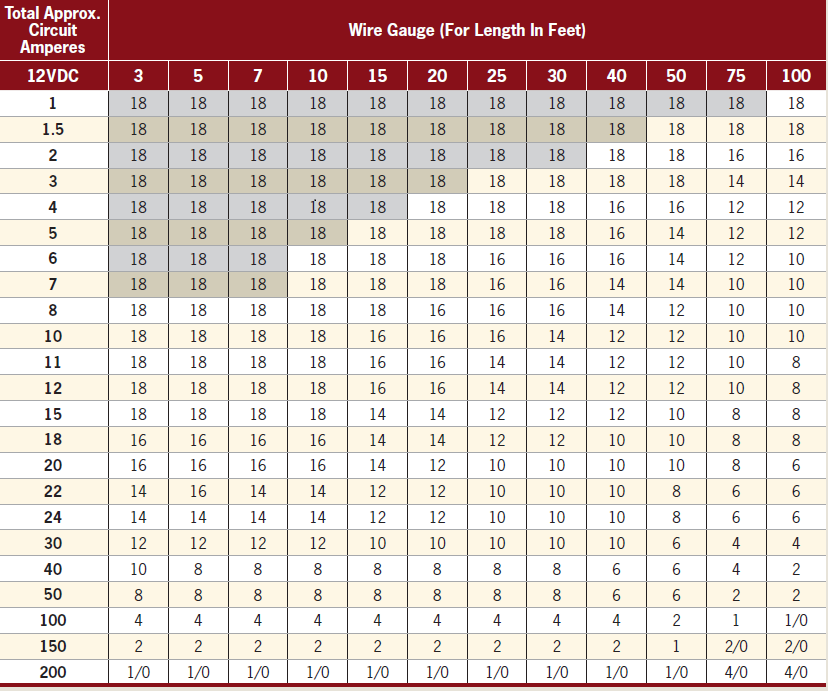
For 3 A from a 24 V source, use good-quality 18 or 20 AWG stranded wire, perhaps in a 4-conductor ribbon cable.
The usual stepper motor cables for diode lasers tend to be grossly under-sized for whatever wire size they claim to be (some don’t bother mentioning that) and might not even be copper, so if that’s what you’re using, now you know why it’s a Bad Idea.
Because the rotary won’t need much holding torque, you should set SW4 Off to drop the idle current to 1.5 A.
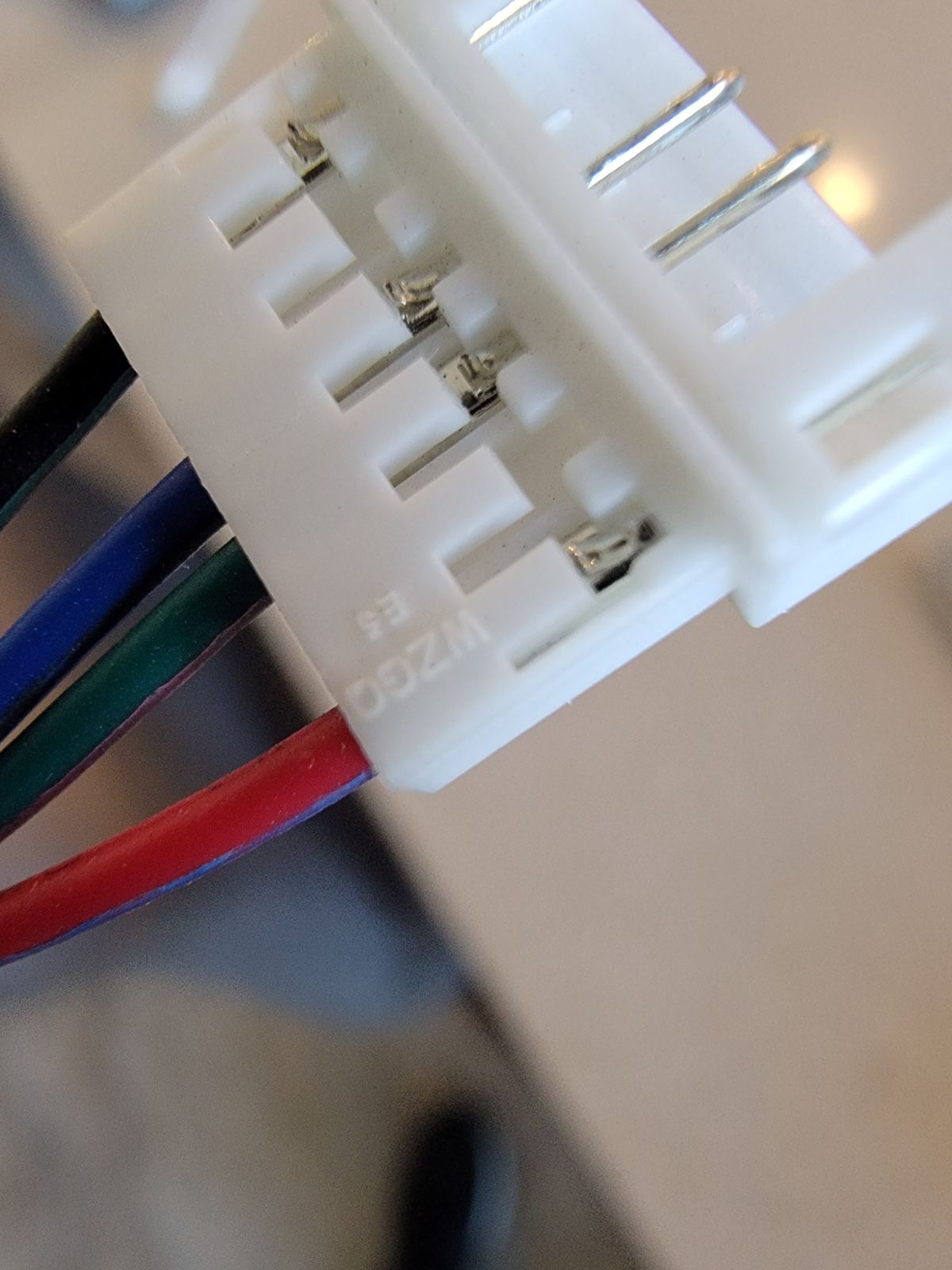
I’ll definitely give SW4 a shot. The motor wires come attached to it, so I have jumper wires between those then to this 4 pin cable. Perhaps the jumper wires are the ones that are too small. By chance do you know what end this is? I’ve exhausted my searches and can’t match it up exactly.
Thank you Jeff. I did order a JST connector kit from Amazon but it didn’t work out for some reason, don’t remember why as it was January lol. I can’t seem to find just the connectors with the notch out of it. IDK if it really matters. These also have a smaller gauge wire, so didn’t go with ones like the links you sent.
Both of those are 26 AWG and grossly under-qualified for 3 A, even if they happened to be pure copper.
If I were wiring that thing, I’d get rid of that white connector and splice the motor directly to the connector on the right end of that xTool cable, which is some flavor of an “aviation connector” along these lines:
Assuming the socket end of the aviation connector is on the laser, measure its inside diameter to be sure xTool hasn’t used some weird non-standard standard.
Exactly what I was thinking. I already have the X-Tool cable, so may just unsolder the wire they have since it’s thin. I don’t think the motor wire is quite long enough so I’ll have to add some in. Now to revisit my notes from Dec / Jan and verify the pinout for A/B +/- lol.
I have some 18/5 solid copper wire. Think that’s good enough?
Ok I’ll grab some stranded. For now just testing with the solid. Traced everything back to the step motor driver / board but now rotary is acting goofy. I ohm checked the wires that I soldered into the aviator plug to verify continuity.
Doesn’t look like I can attach a photo so here’s a link to a video. Quick Share
If you haven’t adjusted the axis acceleration and maximum speed for the rotary, the controller is likely accelerating too hard. The maximum axis speed is also too high, but use a low speed and tweak the acceleration first.
Reduce the acceleration to 10 mm/s², which will be grossly very much too low, do the calibration dance until you get one accurate (slow, steady, ponderous) revolution on command, increase the acceleration by factors of two until the motor stalls out again, reduce it by a factor of two, then work on finding the maximum speed.
I think I got it fixed! When I took the aviation plug apart to put stranded wires in, I noticed some of the other ones had melted sheathing. I believe that happened when I was soldering and didn’t notice they got that hot. I put everything back together with the previous settings and it’s working smoothly. Keep you posted if it starts smoking again lol. Thank you very much everyone!