When I turn my Laser on, it has started doing the RATTLE/HUM Of death. It does this for approx 3-5 seconds then finishes the homing process in approx 1 minute. It does not return to HOME (0.0) it goes to 100mmx100mm, then labels it as home. But if I push it back to the 0.0 position it works seamless until I restart the Laser again. then the same process all over again.
I have tried nearly every setting in the book i can think of. Any suggestions would be appreciated, and much welcomed.
Do you have XY limit switches? If so, are they the kind that looks like a small red box? With the power off, slowly move the head into the middle of the bed area, then power up your laser and, immediately press ESC on the keypad to stop it from moving. Use a hex/allen key to move over the red limit switches to see if they turn on a light inside of the red box. If the light comes on for all the switches, then there might be a misconfiguration of the bed size in the controller, or a bad wire somewhere in the circuit.
Virtually all Ruida machine have homing switches… Ruida controllers are generally not found in low cost lasers.
I’d suggest not doing any changes until you determine what it’s doing exactly.
You might know what this means, but I sure don’t. Especially if you’re hoping for some reasonable suggestion on what to do with it.
A video is great… post it on something like google drive, set protections so anyone with the link can read it and post a link to it here.
Unless the switch is loose, don’t hack this until you have a reason to do so. It sounds like it is homing, but if it’s making noises then it’s likely loosing steps… I think we can eliminate the switches as it would error out during the homing process. If there was a switch position issue, that’s where it would home, not 100, 100
Where does it normally end up after the home cycle?
![]()
Ah, but it’s a homebrew: anything is possible! ![]()
That seems as though it is not actually homing or at least failing partway through. Given that it is not moving correctly, pretty nearly anything is possible.
We loves us some homebrew action around here, but pictures will help dispel our misconceptions about what the machine looks like (and show off your design).
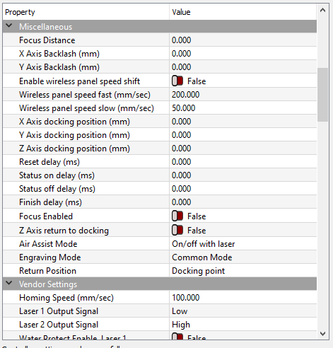
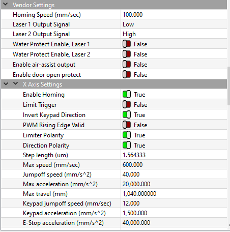
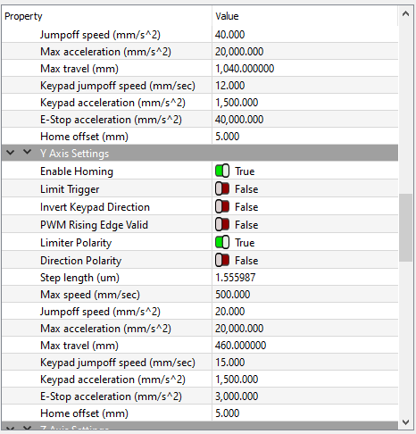
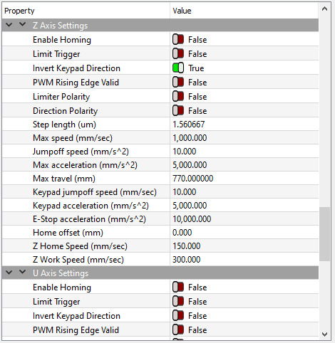
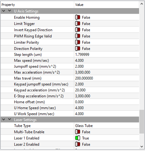
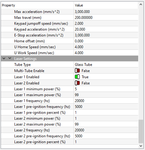
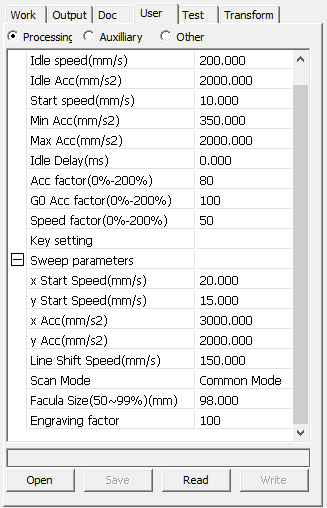
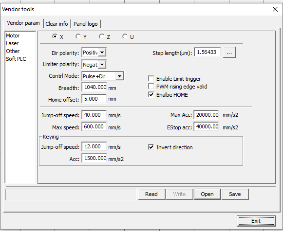
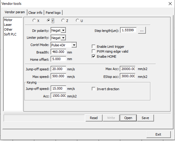
Because you’ve been tweaking the settings, take some screen shots of the Machine Settings so we know about speeds / accelerations / offsets / whatever.
By saying the rattle anx hum of death, I mean the turning of thd stepper motorz in the way they hit the x and y axis when it should be not moving. Meaning it is at the Zero position.
nd when it completes this, it then moves very slowly to the 100.100 position, which is 100mm from the home position.
The switches i have are the mechanical type NO/NC. Currently have the as NC.
That could be your problem unless you tell the Ruida to invert these… These are commonly NO switches and pull the Ruida input pin to ground.
With the exception of motor steps and the pwm, i/o on these are active low. Most of them can be inverted via the Ruida configuration.
Is there no error on the machines console when it boots?
@ednisley if someone builds one of these and puts a $500 or more controller into it, then skips installing home switches, I question their sanity.
![]()
When it finishes the Rattle/HUM it ends up at 100MM from ZERO on both X and Y axis.
I have limit Switches, however they are the Mechanical type. And I admit, I may have the configured incorrectly. But that is a simple fix. Figuring out the rest of it is the complex part.
Especially since this machine has been functioning for over 2 yrs, and I decided to upgrade to a better controller. The previous was a Ruida 6342, K40 Upgrade kit. But I dumped the K40 concept.
I have a boot video of the led’s on the Ruida when it boots…
Does your led’s show the same operation? You should see it operation on the led’s. You can also use Z/U->Diagnosis on the console to see if it’s reading it. It’s manual, like the video.
If possible change your switch configuration, I was sure you can change it but can’t remember. The Chinese documentation intermixes limit and home switches, so sometimes we read it as something it’s not.
If you can’t toggle it in the controller how it’s reading, can you change the switch? Some of these have three connections, common, NO and NC. Sometimes you can just swap a wire to the other pin and invert it’s operation.
I’ll hunt around a bit more tomorrow, when I’m a bit more awake …
Good luck
![]()
The X and Y accelerations are vastly too high:
lower both to 3000 mm/s².
Set the X and Y axis Jumpoff Speed values to 10. Confusingly, the mm/s² unit means acceleration, but the magnitude suggests it’s really the start-from-a-stop speed.
Reduce Homing Speed to 50 mm/s, which will eventually be too low.
You say the home switches are wired as NC, so one of the Limiter Polarity settings is wrong. With the laser head away from the home switches, use the console’s diagnostic display to determine which switch is (incorrectly) active, then flip the Limiter Polarity of that axis.
If I understand the machine layout correctly, the head is homing toward the left rear corner. Ruida controllers typically home toward the right rear corner. This can be configured, but where are the limit switches in your machine?
Assuming the X axis limit switch is on the right end of the gantry and the laser head is trying to home leftward, then flip the X axis Direction Polarity setting to False. If that makes manual jogging work backwards, also flip the X axis Invert Keypad Direction switch to False.
Do those, let us know which settings you have changed, and report what happens.
With no disrespect to @keith1018, I’ve long since learned to never assume the obvious. ![]()
Mine, stock were 6000mm/s^2… It won’t hurt it to lower these, and you probably should while in debug mode. Also lower the pwm … it’s never a good idea to be working out bugs and use maximum settings.
My homing speed is 100mm/s
From the video, it appears the it’s got switches on the left rear and it’s heading that way. Mine homes to the left rear.
I’ve seen them home in at least three out of the four corners, so I’m sure it can be configured for that. I’ve seen a number of machines where they changed it’s home corner. However, none of these people had an easy time configuring the Ruida for this… I’ve never tried.
Right now I can only suggest that it’s not using the home switches properly because of the NC type selected.
Fix that and the other issues might go away. Either in the configuration or physically.
Agreed…
![]()
Ed and Jack,
You are both right, My limit switches were wired incorrectly. So, I changed the wiring and replaced the switches. They are now wired to NO, and appear to be working fine…
I also made all of the changes Ed made previously mentioned. And now the settings are as follows:
X-Axis
Homing=True
Limit Trigger=False
Invert Pad=True
OWM Rising=False
Limiter POL=False
Direction POL=True
X-Axis
Homing=True
Limit Trigger=False
Invert Pad=False
OWM Rising=False
Limiter POL=False
Direction POL=False
Z-Axis (still Incomplete setup)
U-Axis (still unused)
Beam is aligned and laser is doing it thing Lasering…
With these settings, all on the main Platform appears to be working so far. Still need to get Z and U setup. But that is another day project. I have a new 6445-GT5 in route so I can start the next project of a 4ftx8ft true cutting Laser. Looking at 200-250 watt, so I can cut pretty much anything I need except metal of course.
Yes this is a hobby, I am in the US Military full time…
Excellent!
Assuming the machine now homes dependably, you can set both of those to True, whereupon the controller will prevent a job from commanding it beyond the platform limits. In principle, that should never happen anyway, but, in practice, an extra safeguard will come in handy.
Now that it’s working, you can tune the speed & acceleration settings upward from my overly conservative starting points to match the hardware’s capability.
Then go make some smoke!
![]()
I don’t think it works this way. The dsp units checks this normally. As far as I know you can’t disable this.
I think these are for limit switches… can’t really remember… ![]()
My position is and has always been if it works don’t f**k with it…
Have fun ![]()
![]()
Hard to argue with that logic!
My KT332N manual has this to say:
Hard limit protection:Using for whether to enable the hard limit protection function of this axis or not.
On the other paw, the controller doesn’t have input terminals for switches on the other ends of the axes. Maybe that setting enables the controller’s calculations, rather than the switches?
Perhaps I could set up an overly long vector, cut it with that option set either way, then tried not to flinch when the carrier hit the wall. Nah, not worth the anticipation.
So far on the items i have managed to test, it stops exactly on 640mm and 1040MM and does not bang the wall at all…So apparently it is self sufficient by knowing that the Switch side is 0.0 and it only has so far to travel to get to 640mm and 1040mm. that is my take on it anyway.
Next thing is to get the RED DOT pointer setup properly, and smoke extraction done, then on to the next project.
thanks for all of your help and advise, worked wonderful.
As far as I know, this is via hardware…
Yours only has the U limit.
Mine has inputs for X, Y, Z and U that are limit switch inputs. The + designates one of the limit switch inputs.
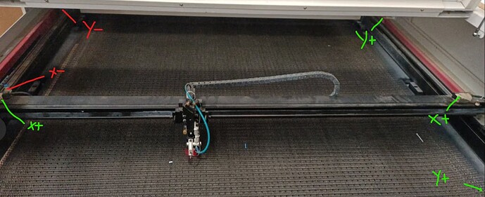
This is the layout for home/limit switches.
Red are home switches, green are limit switches.
Homes left/rear. Note that it takes 6 switches.
Before homing is completed, state of the limit switches appear to be ignored. After homing the home switches are definitely ignored.
Of course we don’t see this much as work area is generally lost, these need to be outside the work area but still within a operational range.
![]()
This topic was automatically closed 30 days after the last reply. New replies are no longer allowed.

