Hi all, just upgraded from Kt33n to Ruida 6442, just the one problem at the moment.
‘home’ switches are getting ignored by the machine.
I’ve checked them both manually and they both light up.
I’ve checked them with the ‘diagnosis’ and both are being picked up.
I’ve checked and double checked the wiring, also checked against pics of others with the same controller.
the machine goes to the stops and light them up but continues to try and run past the frame.
Didn’t have this problem with the old KT controller.
63 years old and refused to do anything with electrics apart from the odd bulb or plug, for some dumb reason, thought it would be an easy little job.
after 63 years i should have known better. ![]()
There is an old thread on here with a very similar problem but there was no solution.
Any ideas would be welcome… ![]()
It’s likely a configuration problem with the new controller.
That means the laser head is moving in the right direction and the switches work, but they must be connected to the correct input pins on the controller.
Which indicators light up? They must be the X Limit - and Y Limit - indicators, with the - sign, not the + indicators.
If that’s what happens, then we’ll need more information / pictures / suchlike to go further.
Some things to check in Edit → Machine Settings → Vendor Settings after homing works:
- Enter the actual platform size / maximum travel distances
- Turn on
Hard Spacing Protectionfor both axes - Copy the speed & acceleration settings from the KT332N
- Ditto for the step size values
Wisely was it written (by my Pennsylvania Dutch ancestors): We grow too soon old and too late smart. ![]()
Thank you Ednisley, i’ll get back to it tomorrow, if no joy, i’ll take a couple of pic’s . ![]()
Hi Ed,
an update.
I got the ‘y’ axis working, as you mentioned, it was the ‘hard spacing’.
The ‘x’ axis still not working as it should, it’s not picking up the hard spacing, pretty sure it’s something I did, or not done.
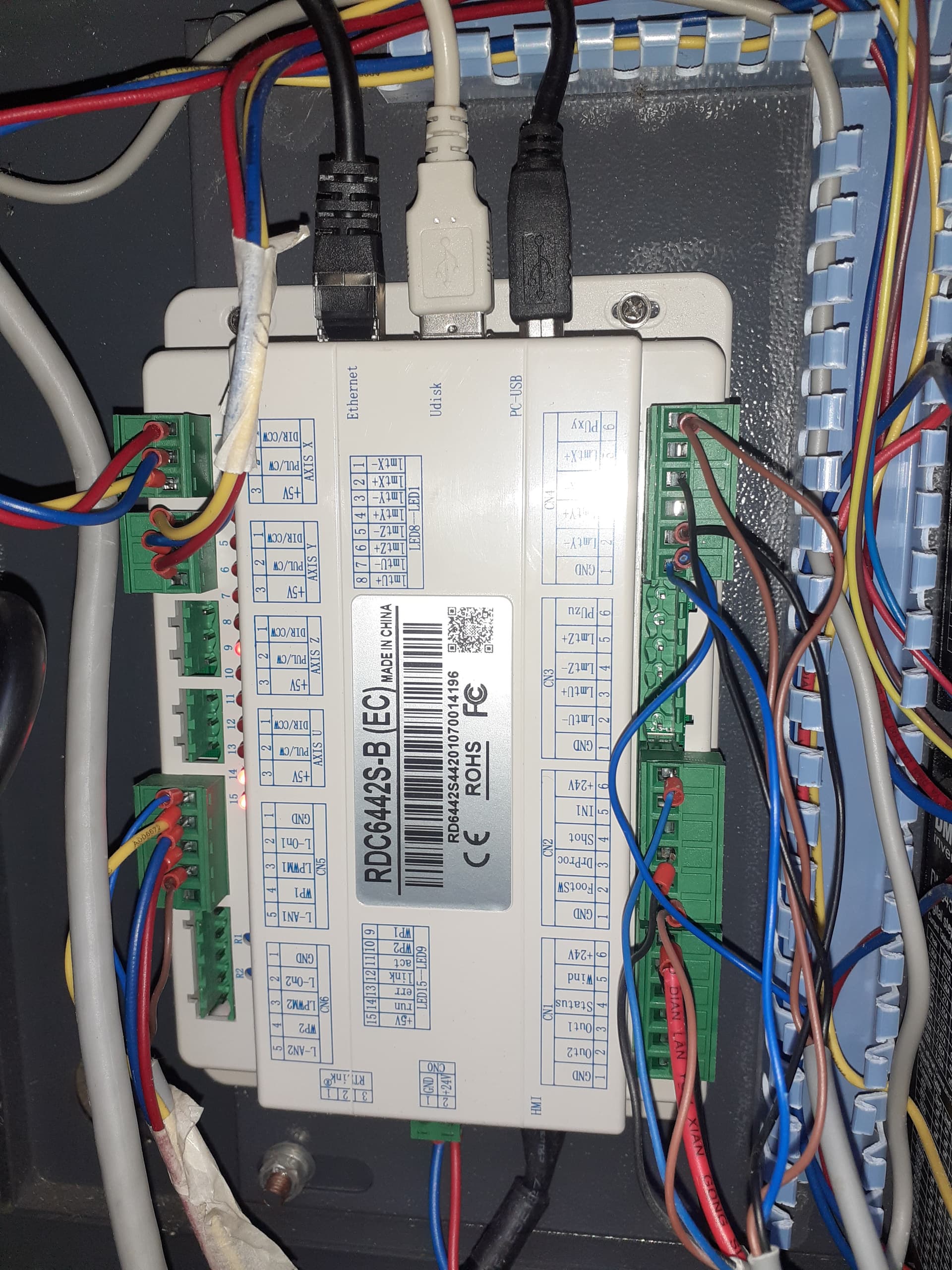
In the picture, the wiring for ‘x’ and ‘y’ axis are the same, just haven’t got the same colours in the same places(may get round to swapping them about).
The ‘y’ axis stepper motor decided to quit, now waiting for the new one.
2 weeks to wait.![]() (having one of those moments in time).
(having one of those moments in time).
That is unusual, because stepper motors are basically dead-simple reliable.
Are you certain the wiring from the controller to the stepper motor drivers is correct?
The wire colors don’t matter, but the connections do. I’d assume the original factory wiring was consistent between the X and Y axes. If you installed one set of wires backwards (as it appears in the picture), that stepper driver won’t work at all.
Hi, the stepper has been on it’s way out for a while.
I tried changing the bearings but made no difference.
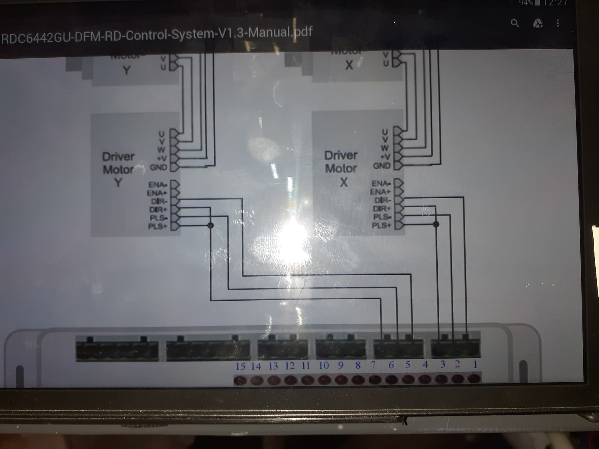
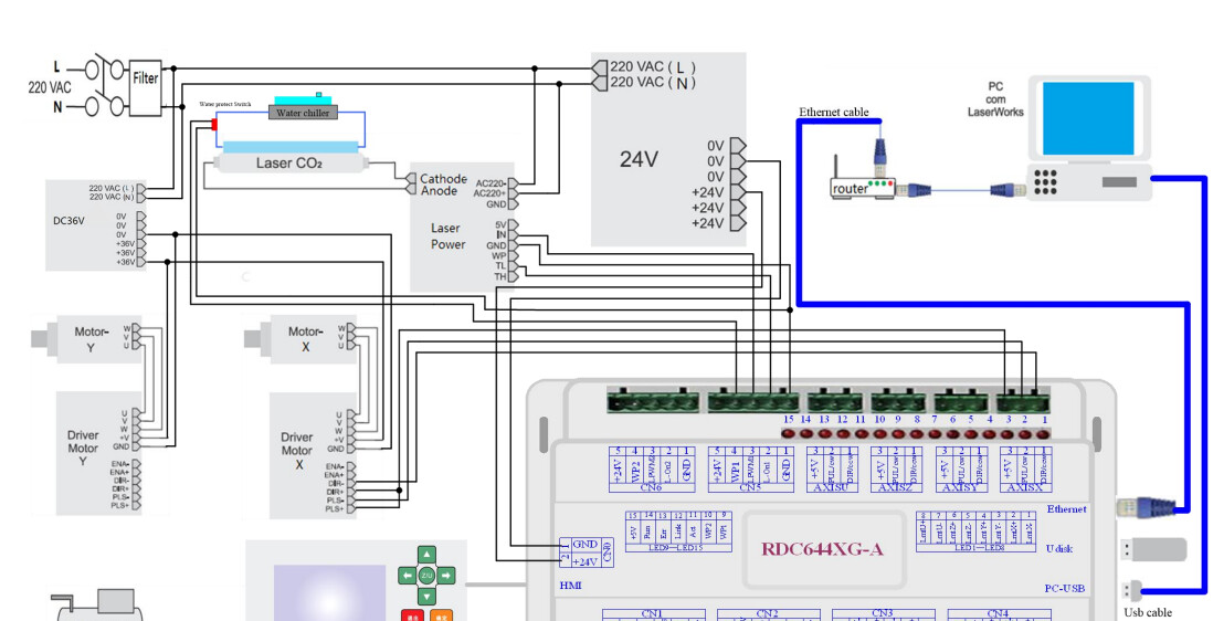
More pictures of the wiring diagram that I had to download with the new controller and a couple of the wiring.
All the colours now match to what they should.
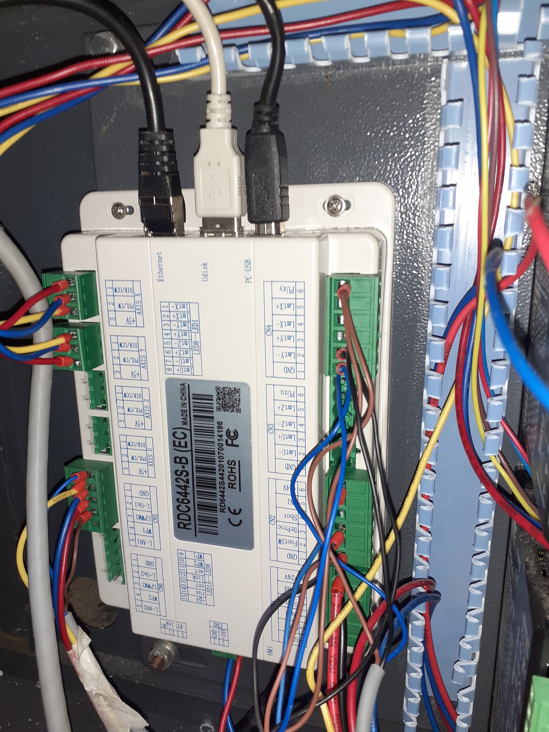
The bottom pic of the motor controller is the ‘y’ axis.
I do not understand why you have interchanged the red and yellow wire colors for the X and Y axis stepper drivers. They appear to be wired correctly, but it would be much easier to verify when you use, say, yellow for both +5 V connections and red for both DIR connections.
Stipulated: I am overly fussy.
If you took the stepper motor apart to replace the bearings, then the rotor has been partially demagnetized and the motor will never again deliver its rated torque. This will reduce its maximum acceleration and almost certainly cause baffling problems in the future.
The stepper motor drivers in the diagram do not match the hardware shown in your machine: the diagram shows three-phase steppers and the machine has two-phase steppers.
How did you determine the wiring between the drivers and the motors? The two motors are different, so the color codes are unlikely to be the same and, in any event, will not match any data sheets you may find for other motors.
And this is what happens when a groundworker plays with electric ![]()
It’s why I’ve always avoided it but hey, I now have time for new things ![]()
Trial and error and more errors…
Just received a new motor, they sent the wrong one(typical)
I believe I’ve been reading from the wrong diagram(more error) although they both state 6442G
Could you tell me if this one seems right.
All confusing to me but all part of learning.
As for the drivers, it all seemed simple enough to me (in my head), just follow the plans (more error)
I’ll see if I can find some to match the diagrams.
Unless you have any recommendations?
Many thanks.
If you think of it as “trial and error and more learning”, well, the whole process becomes more enjoyable.
I can loan you a favorite t-shirt.
As far as the controller is concerned, it sets the DIR signal to select the rotation direction, then pulses the PUL (a.k.a. STEP) signal to make the motor rotate one step in that direction.
The connection between the stepper driver and its motor have nothing to do with the controller wiring, but the motor won’t work with incorrect wiring. The diagram shows three-phase stepper motors with their corresponding drivers, which is not what you have.
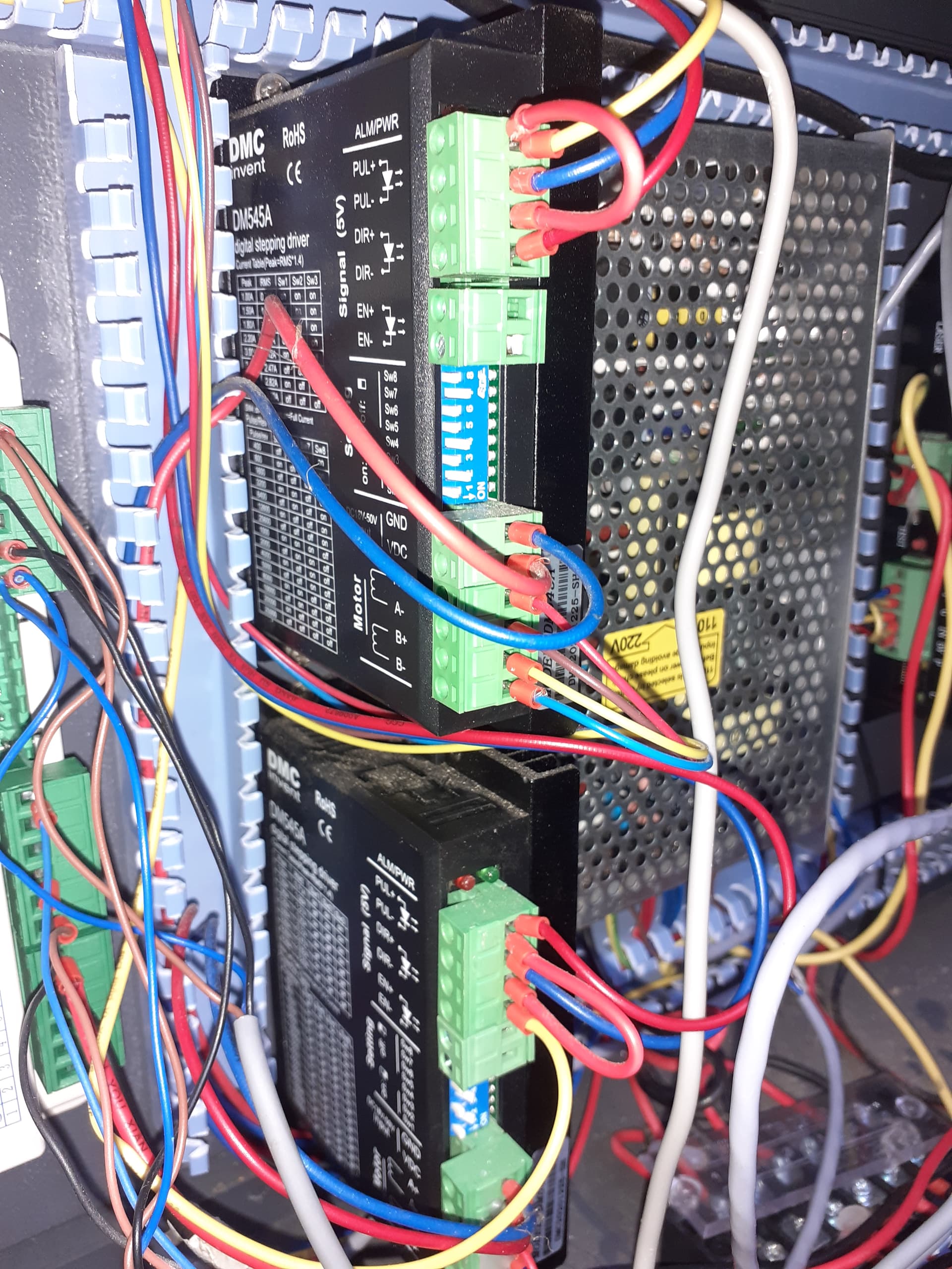
However, the wiring for two-phase motors is straightforward: the label next to the lower connector block on the DM545A drivers shows how to connect the two motor windings to the terminals.
Key point: the wire colors are meaningless.
To check the wiring, get a multimeter, set it to the Ohm or Continuity function so it beeps when you touch the probes together.
With the machine power off:
- Unplug the connector with those four motor wires
- Measure the resistance between pairs of terminals
- When you find two that measure a few ohms (the
Continuityfunction will beep), you just found one motor winding
Those two terminals should correspond to the label sketch for A or B. Verify the other two wires have a few ohms resistance, which means they are the other motor winding and should go to the two terminals not used by the first pair. Plug the connector back into the driver.
Repeat that for the other motor driver, keeping in mind the colors will be different.
What you should find is that the windings match the diagram. If not, report back! ![]()
Did you check the motor driver current settings with the switches?
Mine was set to double what the steppers were rated.
![]()
The photo shows SW1-3 = 3.3 A, which is reasonable.
SW4 calls for full idle current, but that’s in the nature of fine tuning.
The top driver is set for 5000 step/rev, which is fine. Dunno about the lower driver, but we’ll get to that.
Do you know which motors he’s using?
I have the holding current (switch 4) turned off for 1/2 current…
The manual states ‘Theoretically, this will reduce motor heating to 36% (due to P=I2R) of the original value*’
m545-motor-driver.pdf.txt (307.2 KB)
![]()
Given that it’s an OMTech 80 W, I’ll assume it has garden-variety NEMA 23 steppers and anything around 3 A will work.
Despite the name, that’s for the DM542 stepper driver.
AFAICT, the DM545 and DM542 sport the same switch settings, although they probably differ in maximum supply voltage or diagnostic blinkery or some such.
Hi, sorry it’s taken a while to get back.
Seems like both my family and the missus family have been waiting for me to retire, I now have lists of jobs to do.(should have stayed at work) ![]()
Anyway, the hard stops are working(both x and y) my wiring was the problem.
Swapped out the ‘y’ motor (Nema 23), nothing changed, power is there, it tries to run but gets nowhere.
If i try reset, the motor runs but just grinds, it sounds like it’s getting too much power and ripping across the belt.(I replaced the belts a short while back)
I left it trying to run while I checked it wasn’t slipping across the belts, it wasn’t.
I’m guessing a power problem, both ‘x’ and ‘y’ switches are set the same.
I’ll read up on the switches and get back as soon as I can.
Many thanks for the help, much appreciated. ![]()
This is almost certainly the result of the speed or acceleration being far too high for that axis: the motor cannot handle the step pulse rate.
Take screenshots of the Edit → Machine Settings → Vendor Settings for the X and Y axis so we can see what’s going on.