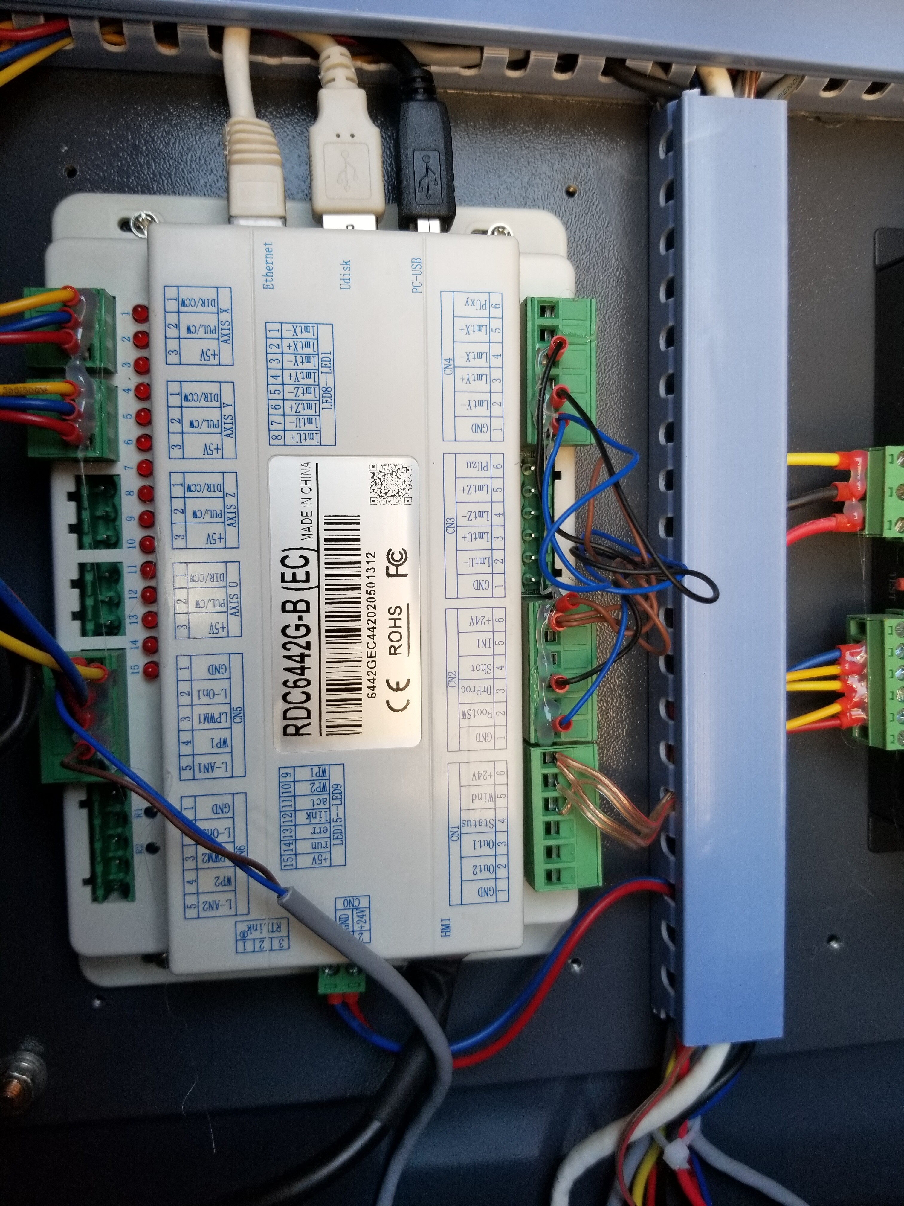
I’m having some issues with my laser not firing, even when pressing test button on PSU. The PSU and tube are new. There are some LED’s on the 6445G that are lit up and I’m not sure if it’s related. I see the title of the LED’s on the control unit but there’s limited literature on what they actually mean.
LED #
15 - On solid
14 - Blinking
12 - Solid
11 - Seems to randomly blink
3,1 - On solid unless I push the actual limit switch, then it goes off. Seems backwards to me.
The water protection light will turn off when the 5200 is off, then light up when the chiller is running.
I do not have the water protection wires plugged into the laser PSU but they are plugged into the corresponding plugs on the ruida unit. Not sure if this is related to why the tube won’t fire.
Hi Rhett. Has it ever worked?
I noticed you stated it was a new psu and tube. It would be nice of you to post what the LED were instead of their pin numbers. It’s more work for us.
If you look on your controller it says:
LED state pin
5 volts on 15
Run blink 14
Link on 12 link connected
Act blink 11 activity on the link
LimX- * 1 Limit X
LimY- * 3 Limit Y
All of these look normal except the limit switches. They should only toggle when it homes. Unless you changed something related to them, that’s probably not an issue at this point. If the machine will home, X & Y limits are working.
If all you changed were the PSU and tube the issue must be there.
How do you have your laser connected to the power supply?
I’m also confused about your water protection. Is it enabled?
Do you have it enabled somehow on the PSU? I have mine run though the controller, so I didn’t do it this way.
However that input to the PSU needs to be addressed if it has a WP circuit. I don’t think you can let it float. As far as I know there are two inputs for the PSU to fire. One is the laser enable (LOn1) goes to L on the supply. LPWM1 goes to IN on the supply.
Thanks, Jack. I wasn’t sure what the LED’s meant and the manual doesn’t give descriptions. It’s a used custom machine and I bought it knowing the PSU and tube needed replacement. X,Y home correctly and machine jogs and seems to operate just fine, it was just the LED’s throwing me off.
The tube is connected with the cathode or anode, not sure which, going through an amperage meter.
PSU IN to Pin 3 on 6445G (LPW…)
GND - Pin 1
L - Pin 2 (Lon)
Water protection is enabled on the Ruida and wired like you instructed in my previous thread. Nothing for WP is hooked up to PSU itself.
At this point I’m concerned the PSU is dead on arrival which is hard to believe. The bulky white threaded connector between the PSU and tube seems suspect but I would probably have to cut the wires to check. I also bypassed the amp meter thinking it was bad. Still nothing when pressing test on PSU. PSU shows 110V with meter. I thought test button on PSU bypassed everything and just triggers laser to fire?
This is the water protection on the power supply. It needs to taken or held low. It may not fire with the test button if the WP circuit isn’t active (low.)
I think this is how my power supply is laid out.
H: Laser output control (high level effective)
L: Laser output control (low level effective)
P: Water protectio switch (valid if grouded)
G: Ground signal
IN: Laser energy control signal (0-5V)
5V: Output 5V/50mA
The big connectors are probably the HV connections. Leave them alone unless we have to go there.
Jack, I owe you another one. P was disconnected on power supply. I connected it to Ruida WP and the laser is firing correctly in accordance with chiller being on/off.
I have an amp meter for current, but not sure about voltage. Doesn’t the RT link measure that? If so I’m missing the three prong connector on the Ruida. I’ll have to track one down.