Ruida running a Diode

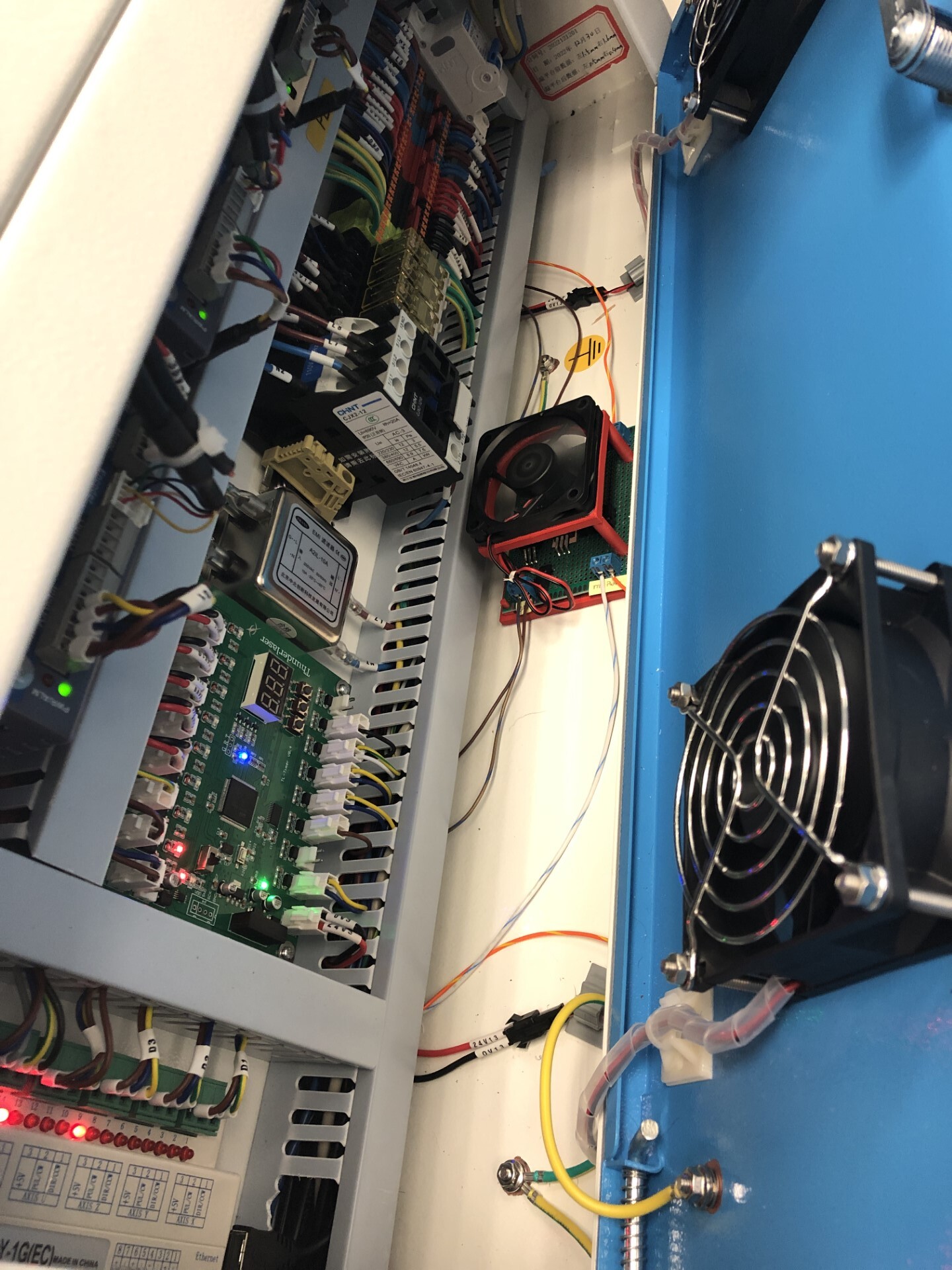
I didn’t check the actual wiring, but the resistors appear to be brown, brown, black, which is 330 ohms… Am I reading this wrong? That would make it draw about 15mA, which is within specifications… the 4k7 would be about a ma…

Why?

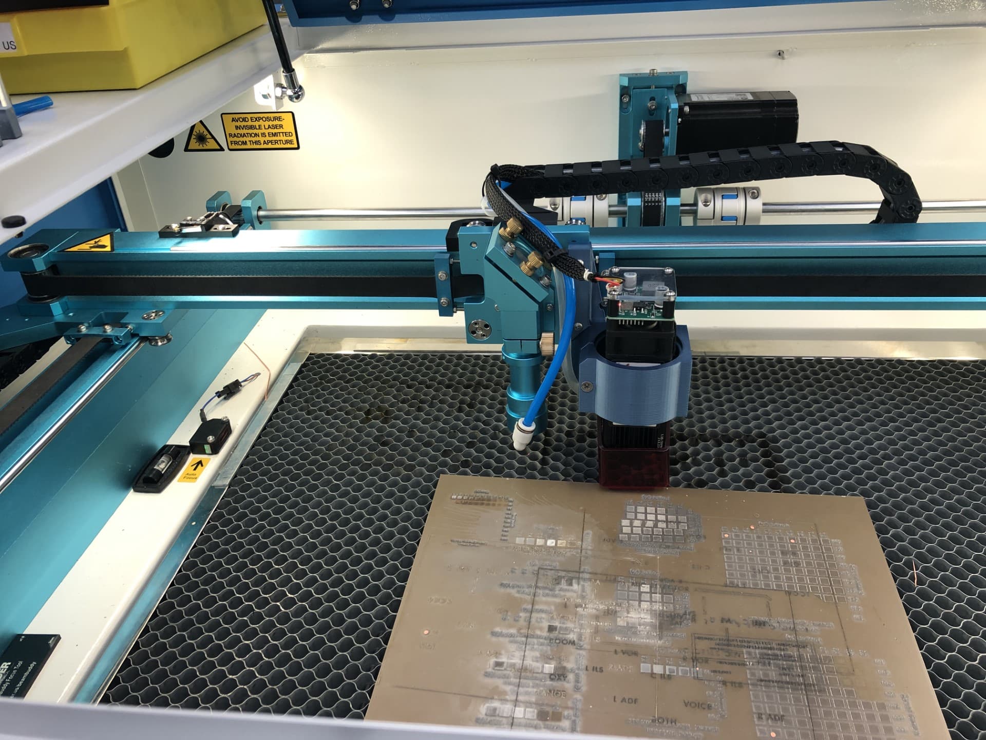
Changing Laser 2 should not break laser 1…?

Clear up the logic here… you have a working Ruida controller… you build a piece of unknown/untested hardware and when it doesn’t work you want to change the Ruida?

You could have easily tested this on your workbench and left the Ruida out it until you had enough confidence it was working…


This is a very simple mechanism and you have many tools others don’t. You are dealing with only two signals…

Your problem is your hardware, at least for now…

It’s should be easily connected to laser 1 that is working (?) to test it.

:smile_cat:

I got it working! My interface card is good. I didn’t enable multi-tube in LB so its working. I really appreciate the help from you guys.

That’s great :wink:

It’s relatively easy to check small logic boards before they are put into service…

Once you known it’s working, the follow it backwards…

Congratulations… Do we get to see a picture… I was a dummy and took it apart before I thought about a photo…

:smile_cat:

Sure can here is the new head all mounted up and the interface card mounted with a cooling fan.


Excellent… thanks so much for the photo… I love seeing these…


What does the Thunder laser board do, that is between the EMI filter and the Ruida?

:smile_cat:

It a timer control board. Its used to time the Air assist, compressor and vent fan.

Thanks… Rather a large board…

I don’t know how they time these… most of us just turn them on … :crazy_face:

Good to know.

:smile_cat:

This topic was automatically closed 30 days after the last reply. New replies are no longer allowed.