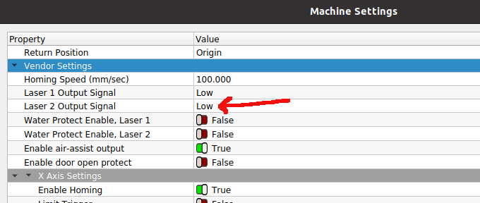
I’m new here and I done know if this is the correct spot to be posting this. I apologies if I’m wrong. I have a bit of a situation. I am adding a diode head (FoxAilen 20w 445nm) to my nova 24. I currently have it running to my second channel on the Ruida controller driving the PWM off of LPWM2 and it fires and is controllable (power levels) but it will not turn off between movement on a cut. I’ve tried changing the machine settings to both RF (preignition/no preignition) and it will not fire. The laser is PWM only. I want to know if I’ve got the machine settings wrong or missing something. I had the thought of possible building a small gate circuit to gate the PWM signal using the L-On2 pin to turn off the laser in between. I’ve put a scope on the L-On2 pin and im not getting anything other than a steady 0.290v no matter if I change it to High or low output signal in the vendor settings.
This is because Ruida controllers use the L-ON signal to disable and enable the HV laser power supply, while the PWM output continues to run all the time.
That’s exactly what you must do!
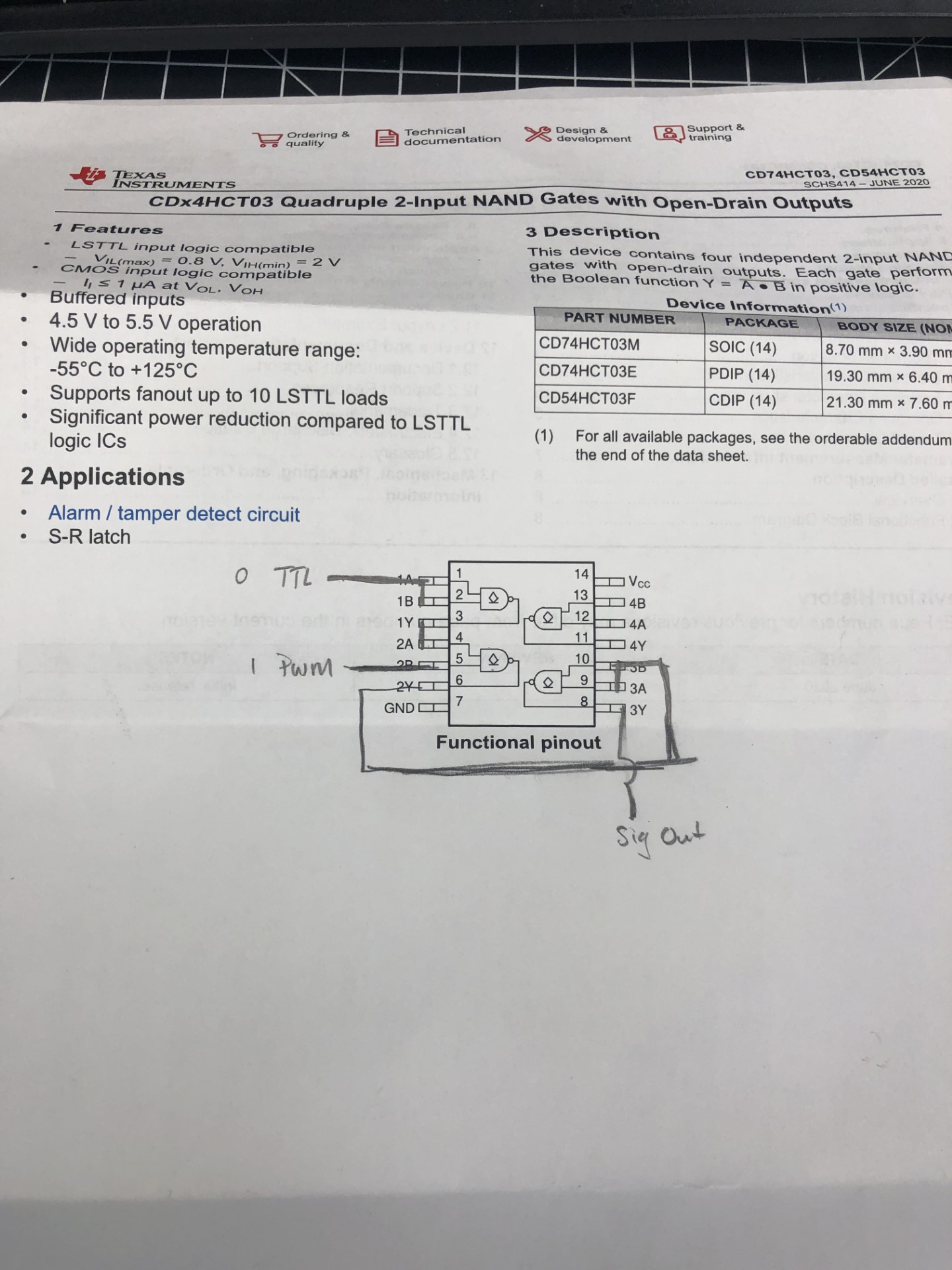
The L-ON signal is active low and the PWM output is active high, so:
Combine the two signals with a NOR gate
Use another NOR to invert the output to be the gated PWM signal
The controller outputs are open-drain transistors, so you must add an external pullup resistor to +5 V in order to get logic signal levels. Anything from 1 kΩ to 10 kΩ will work fine.
Okay, I built a gate circuit using 3 NAND’s and no luck. I tried changing the machine settings (Glass Tube, RF (with pre-ignition), RF (w/o pre-ignition). I tried laser output signal under vendor settings (Low and High) as well with no change. The diode is firing when I manually move the gantry and nothing when I start a cut. Is the pullup resistor necessary for the TTL signal to be present going into the gates. ?
Don’t do this kind of stuff… this has nothing to do with the actual control signals you need. It is working properly as is.
The only thing that could benefit you is the ability to invert the LOnX signal… Cannot do that with the pwm, but you can with LOnX.
Another issue, is these machines are ttl, you are driving it with cmos… Generally you can get away with this, but a ttl output will generally handle more current that a cmos device, so to speak.
Add to that you are using open collector (drain), so the logic line between each gate, probably needs a pull up.
The signals are there without the need to modify them… changing configuration around is a waste of your time.
Do you have a scope or voltmeter you can check what the states in your logic are…?
I replaced the co2 head with a dpssl module, never dawned on my to use laser 2 controls
So I should keep the LB setting to glass tube and signal low?
I have both. on the scope, Pin1-4 nothing, Pin 5-PWM signal, Pin6 nothing, Pin 8-10 nothing.
On the VM, Pin1-2 0.231v, Pin3-4 0v, Pin 5 .331v, Pin 6, 8-10 0v
I put 4.7k pullups on each of the outputs and its not gating the laser. Turns on and stays on during a cut when the output signal is HIGH under vendor settings and nothing from the laser when the output is set LOW. Are there any settings I should check in LB?
Would the 74x00 require the pullups at each output as well?
Put it on the bench and manually pull the input signals where they should be, to ground or to 5V… the output should reflect the correct logical operation…
You can manually do every step with this and correct it before it moves to the real world (Ruida).
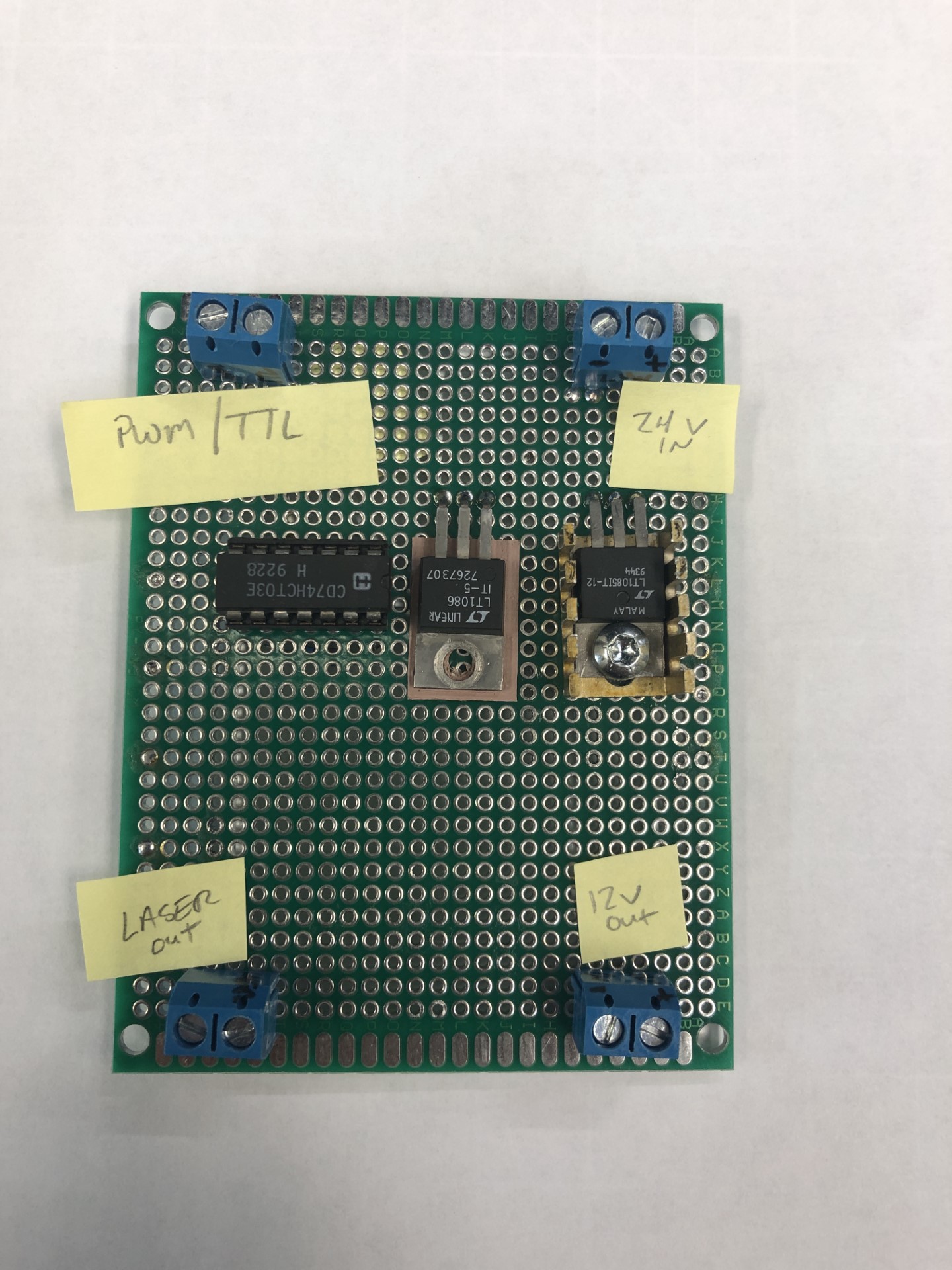
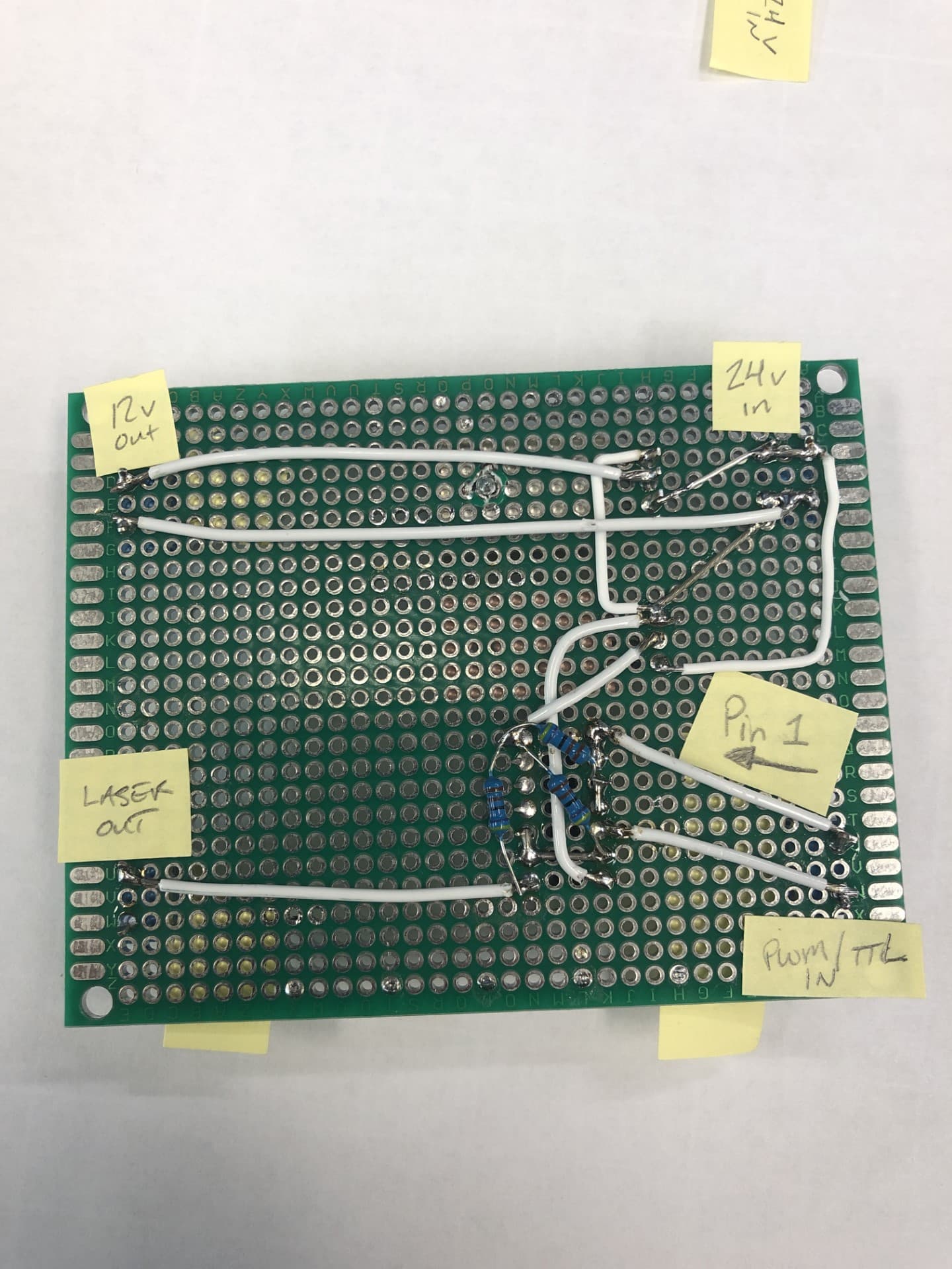
Do you have a photo you can post of this diy chip/build?
The gates are good. I swapped channel 1 over to 2 and copied the settings of 1 to 2 and the CO2 laser would not fire. Could the manufacturer have disabled the second channel?