According to a quick search, your device uses GRBL which implies g-code output for operation. It’s not what I’d consider to be an optimum solution, but you could manually edit the code in the appropriate locations to change the height.
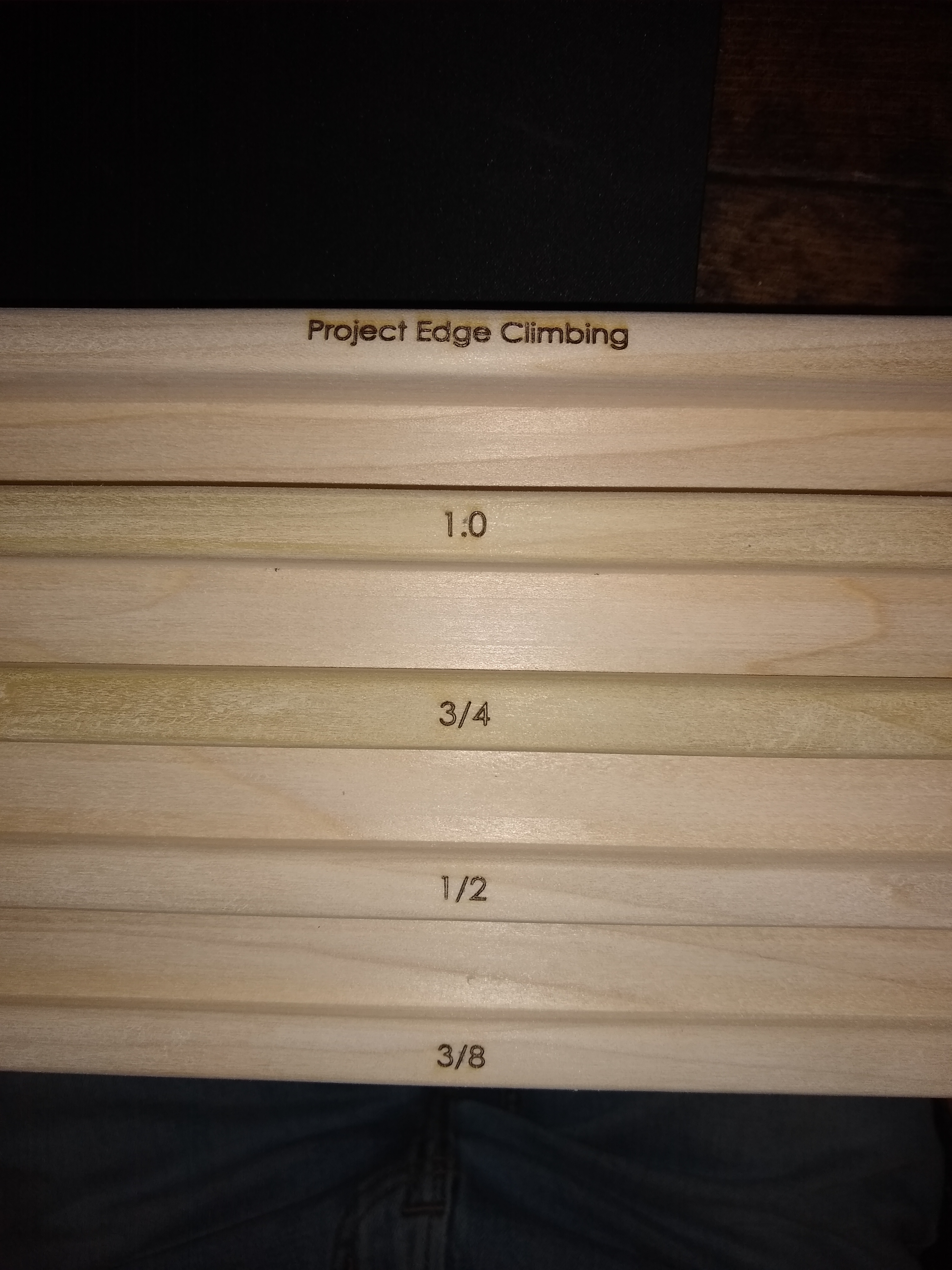
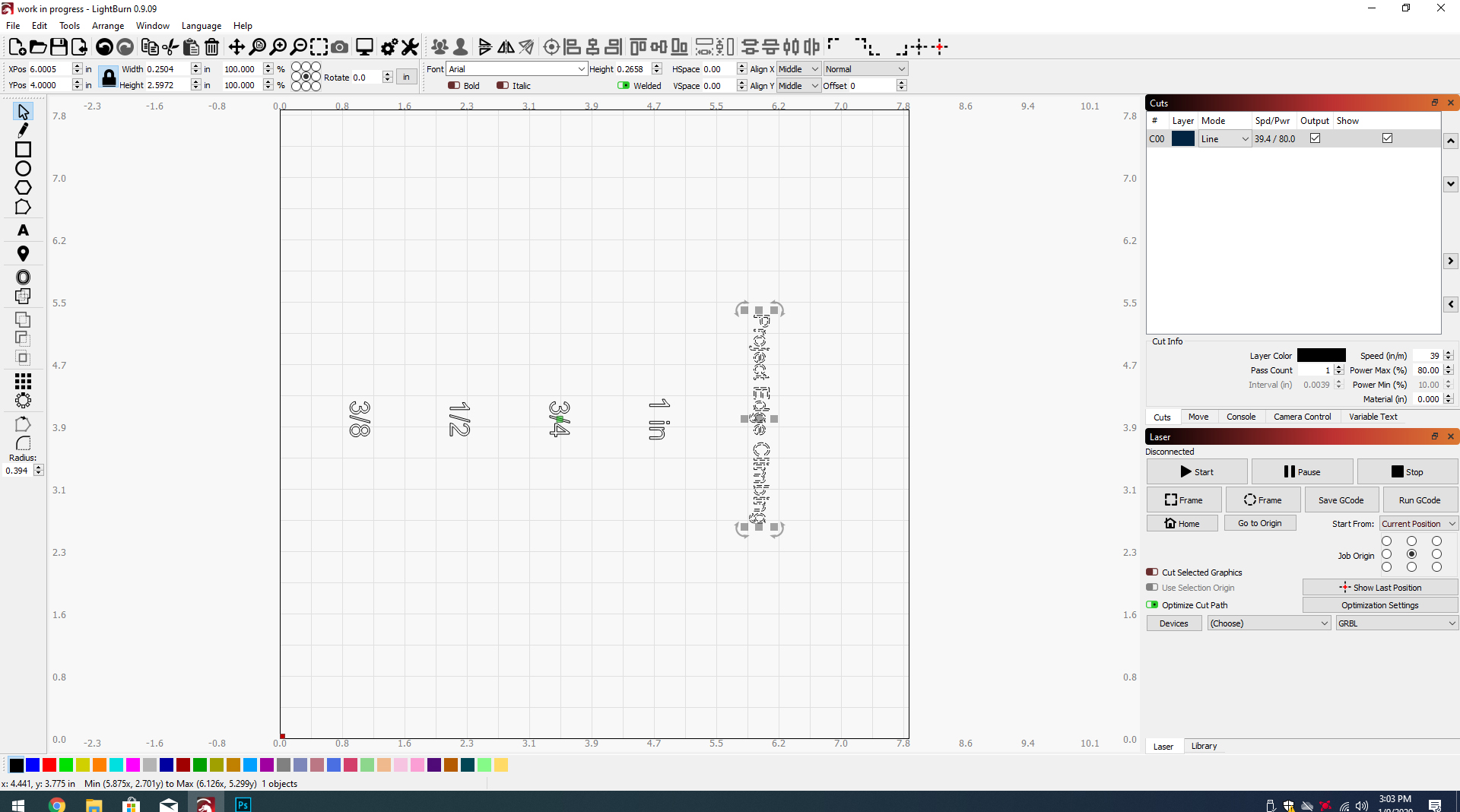
If you’ve used the tool to mill parts at different heights, you’ll see a code reference Zxxx with a Gxxx code preceding it. In the image you’ve provided, there’s a substantial Y movement between the burns. You’d insert your Z adjustment after the Y movement but before the X movement, to prevent crashes if the later moves are lower, although with a laser that’s probably not too dangerous. With a cutting bit, you don’t want to lower the bit until you’re on the spot.
The above is a layman’s approach, guided by minimal understanding and maximum ignorance. Other methods may be better suited to a solution.
Probably not the answer your looking for.
When I run into a situation like this; Cut 2 small blocks of the correct thickness for each piece that is lower to raise them all to the same height and get after it. Of course that means you need the saws that will make this a 5 minute job. I kinda figure that the 5 minutes taken to make wood blocks is not as long as it would take the laser to move up and down on each part if I set it all up correctly, not to mention the time it would take to figure it all out.
LightBurn does provide the ability for you to accomplish what you are describing. You would need 5 different layers with 5 different ‘Z offset’ values, each one lowering the bed more than the last. Z Offset: Specifies an amount to offset the laser head (or bed) for this cut. Useful for defocusing, or pushing the focus point into deep materials for cutting.
Could I define the z offset values in photoshop or would the 5 different files need to be added individually to LightBurn, and individually adjusted? My concern with the latter is that they all need to line up in respect to each other, something I know how to do in photoshop but not lightburn.
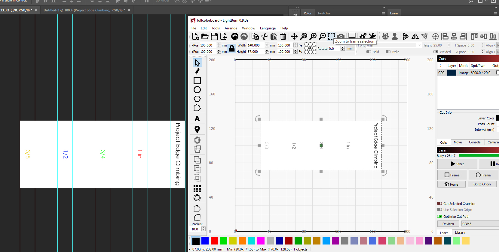
The ‘Z offset’ value is a unique value known only to LightBurn in this context. You can assign colors in the original art which will be used to create the separate layers when imported into LightBurn.
You can create a single file with all five unique objects, each object being a different color and aligned as you see fit, then save that file in one of the LightBurn supported file formats. Import that file into LightBurn and you will see that each color you defined in your source art has been assigned to a corresponding layer. Each layer has its own settings for how you want that object produced when sent to the laser. This is where you set the ‘Z offset’.
If you haven’t already, these are good to review to better understanding LightBurn.
I also find the videos on our YouTube channel have helped others as well.
You can do this within LightBurn easily enough though. Try this workflow…
Type your text
Select and Duplicate (Ctrl+D)
Use the Y coordinate edit control + (alignment offset) to move it by a fixed amount
Edit new text
Repeat until you have all objects created
Select one object at a time and assign to a new layer
Double-click layer color in ‘Cuts’ window to set ‘Z offset’ for each layer
(Hint - Advanced: You can also copy and paste cut settings to speed the process)
Is that an image file you are trying to import? I should have been clearer, auto-assign to layer based on color is for working with colored vector objects.
Did you try my workflow yet? It would be much easier to produce this directly in LightBurn. The one change to my flow…your work is oriented in the opposite direction so adjust the location using the X coordinate instead of the Y coordinate edit control as identified above.
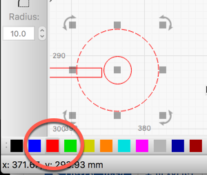
With an object selected, pick a color at the bottom-left of the LightBurn screen. Select a different object and repeat.
You might want to review some of our How to / Getting started videos from our YouTube channel to help with understanding. This post provides a starting point.
Thank you! I found the layers like you said but I am still not sure how to assign different z values to it. I dont want to assign a z position but rather tell the machine to move down “x” distance from starting point.
I do not know. Please remember I can not “see” your system. I do not own one and have zero personal experience with this unit. I want to offer you help and do my best to ensure you have an enjoyable experience using your laser, but I can not learn what is required for you. This is the Y part of the DIY laser journey.
You started this post asking simply “to print these 5 pieces in one run.”. I am sorry, but I think I should have provided a different answer. The more accurate answer would be something more like, “Well yes you can. If you have the right equipment, have it configured correctly and are familiar with the general workings of LightBurn, it is a snap to do what you are asking.”
Given where we are, let’s assume I do have a unit. Questions I would ask now include, does this unit have a motorized movable bed or movable head mount for the laser? Can I move it? Do I have it configured to move in my firmware? Is there information listed in the vendor’s documentation? Have I looked for this information using the vendor’s support resources?
If I do have motorized Z-axis control and firmware configured, how do I have the device profile set up in LightBurn? Have I enabled Z control within LightBurn? Have I looked in the LightBurn documentation? Have I searched for information about my unit on the LightBurn forum?
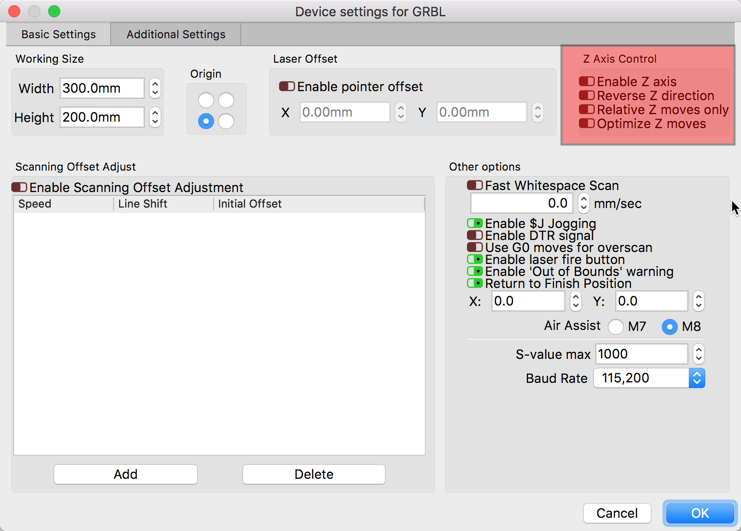
That screenshot was extremely helpful. The only thing I needed to do was enable Z- Axis. I assumed this would be automatically enabled. Is there a reason it comes disabled?
Hi Rick,
I have my z table and lightburn working for z offsets. The issue I have/see is it moves from starting Z to offset then makes the cuts. When there are a bunch of cuts on that layer, or fills, whatever, it returns to “home Z” then back to the offset every single time it jumps to a new spot. Is there a way to make it stay at the height for the layer offset chosen and do all cuts at same height ??? Thanks!