Sainsmart Genmitsu 3018 Prover suddenly stopped working

Hello,

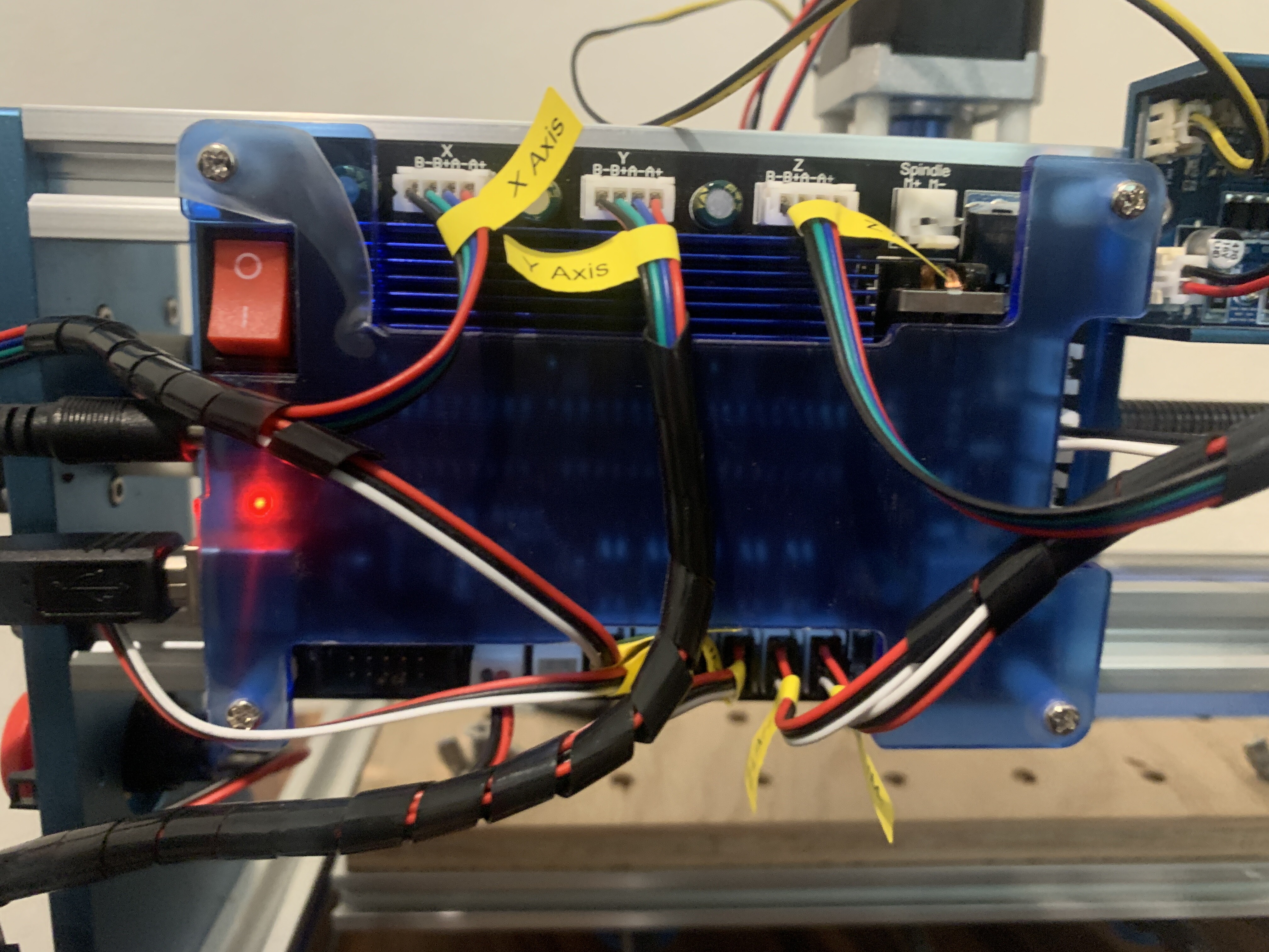
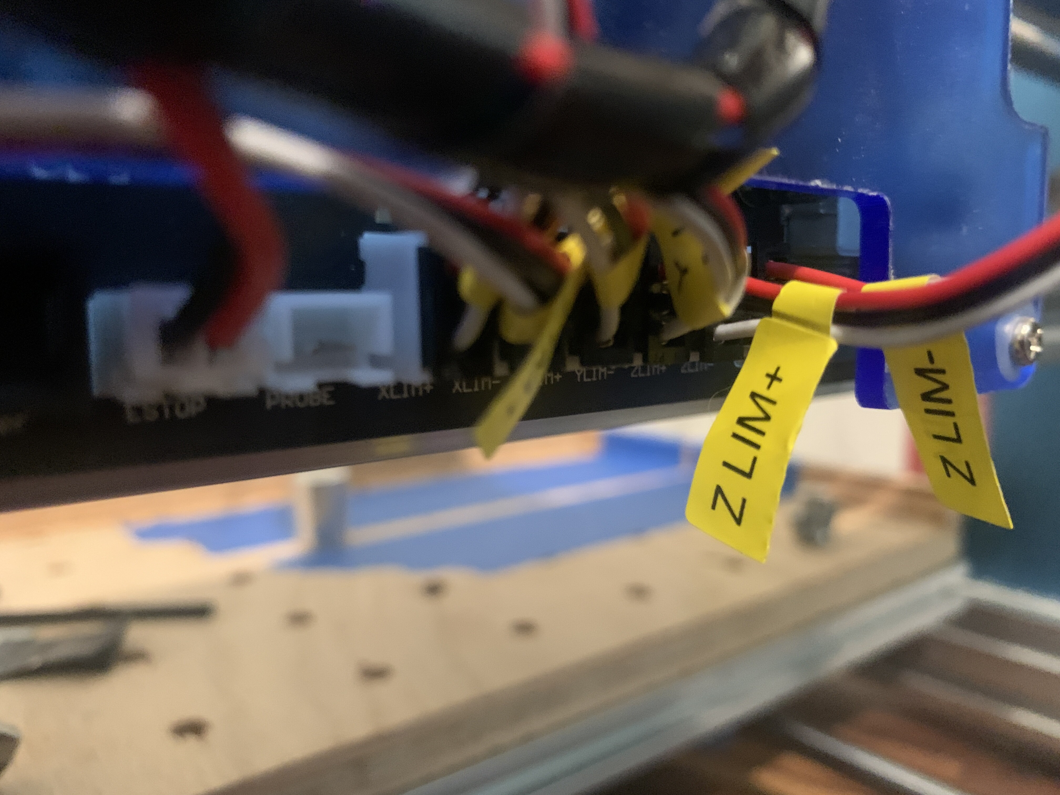
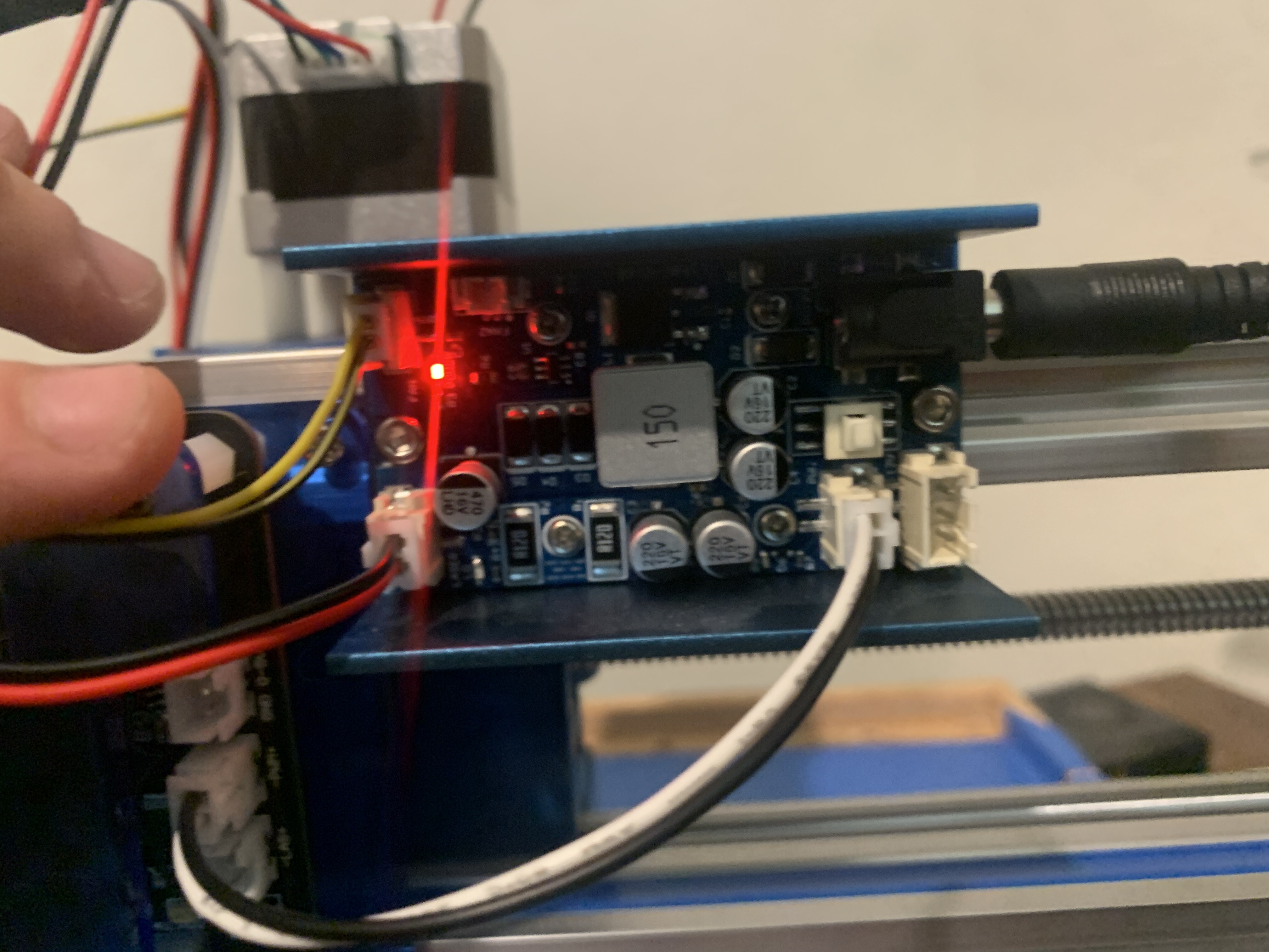
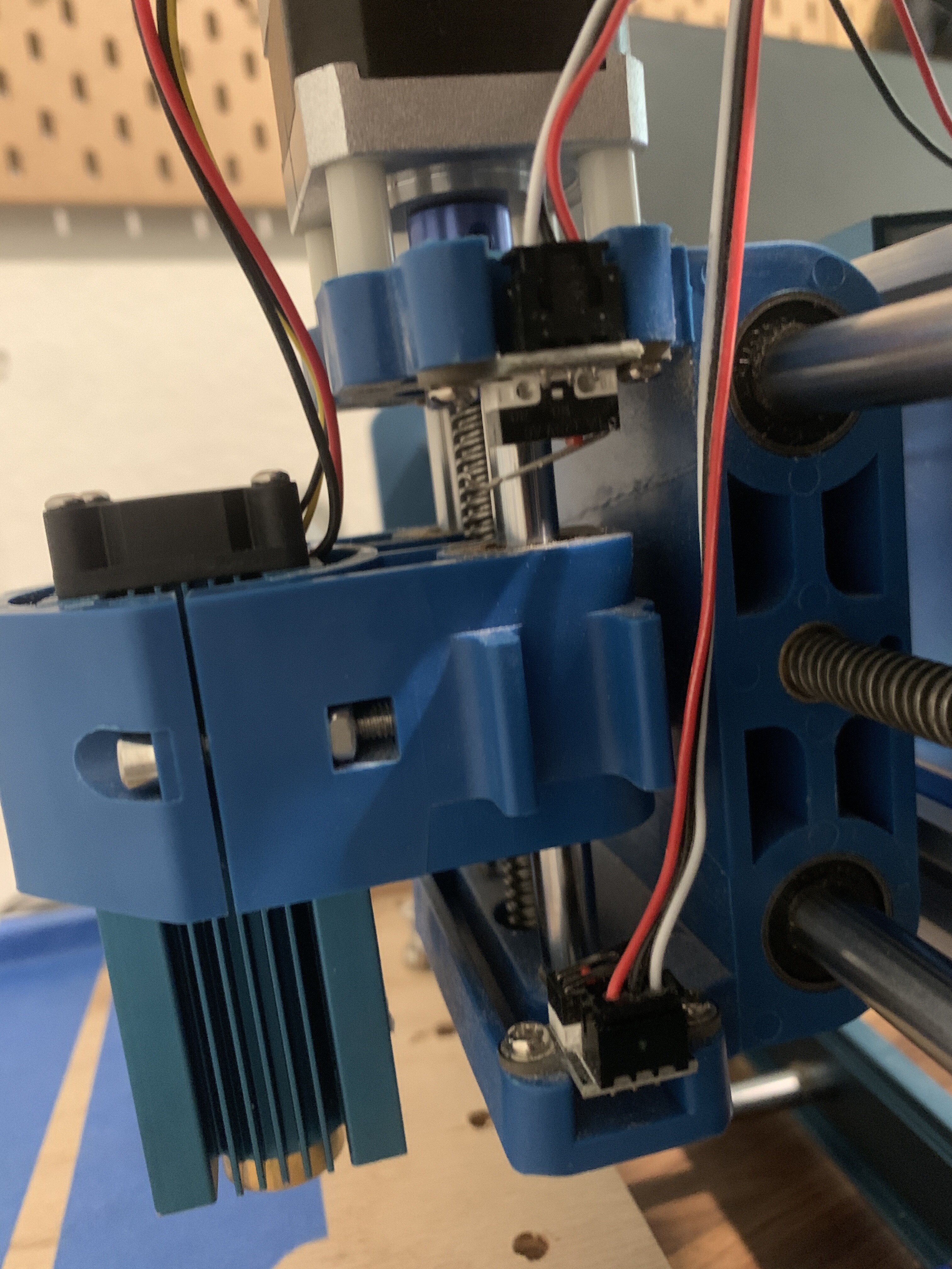
I am new to using my laser and cnc. I have had them for a couple of years but rarely use them. I have the laser module for the Sainsmart Genmitsu 3018 prover cnc. It’s worked on several occasions with no issue so I tried to use it again last night. I homed it without issue and tested a single line burn. It worked just fine, homing switches turned red when hit and laser carved as predicted. After the program ran, I tried to run it again but this time the laser wouldn’t come on and the homing switches no longer turn red or activate when being pressed. I’ve tried everything from updating firmware to reverting back to the factory settings. Can anyone help me figure this out? I’m ready to just throw this thing away after hours of debugging.

Some of these controllers get enough voltage from the usb connection, but the main power needed for everything else may be off or not working…

Double check that it’s getting voltage… If you normally see the home switches light up, and that’s not happening, then I chase down the power loss…

:smile_cat:

Thanks for the quick response. I tried plugging it into a different socket, power strip and wall plug. No luck. The machine still moves X,Y, and Z but the laser doesn’t fire (even when pressing the fire laser button or sending the g code command) and the switches does respond. Is there anyway to check if the switches are sending alerts to the board?

You can manually activate the switches…

The head moved toward the switch at a specified rate, when it hits the switch it will back off then re-engage for a higher precision home…

So each switch has to be pressed twice…

One the machine has homed… you should be able to connect and communicate with the board…

Once it’s home is complete (manually or not) the switches are viewed as limit switches, so if you press them again, the board should give you an error…

Can you drive and do you have a voltmeter?

Good luck

:smile_cat:

When I manually press the limit switches nothing happens in the console. No errors or anything. The machine will continue to move wherever it’s sent even when I press the switches manually. None of the 6 switches work anymore. The homing sequence won’t finish because it just raises up continuously even after it’s reached the limit switch and will continue to grind the motor until it has timed out. Pressing the stop button on the computer and the emergency red button on the machine don’t do anything once it’s started homing. Even turning the machine off during the homing doesn’t reset it. Once it turn it back on it continues to grind the motor until it times out. Everything was working just fine, no settings changed or anything unplugged, then it just stopped working.

I have a voltage meter but I really don’t think the issue is power. If I can move the machine and send it commands it should have enough power. I feel like it’s gotta be some setting that got flipped randomly.

Ok new development: you were right, it needed more power. I realized I had the laser plugged into the wrong spot and no additional power supply to the laser board. Now I can get the laser to fire by pressing the button on the back (still won’t fire in the software). Still no power to limit switches. I’ve tried using $10=19 and ‘?’ But I don’t see any ‘Lim’ outputs. Still won’t home without crashing into the top and grinding the motors

volt/ohm meters are not limited to voltage measurements. They have many uses including debugging your limit switches…


If your switches light up, and they don’t now, it’s pretty indicative of a power issue… Either not enough or some kind of flaky connection on your machine.

You can measure the voltage on the pins of the switch, referenced to ground and see if one of the pins transition to a different state when activated…

Can you post a photo the one of the switches… very low chance that all of these switches failed at the same time.

My basic CNC3018 only had three switches, one for each axes… did you add the other three?

:smile_cat:


Here’s some photos of the equipment I have. I didn’t have a chance to test the limit switches this morning but will when I get home. I even tried different power cables and still couldn’t get them to light up. It also seems the PWM signal isn’t going to the laser from the original circuit board. Maybe a power issue as well.


If you have a volt/ohm meter, you can read each switch.

In your case there’s about a 0% chance all of these switches have gone bad at the same time.

They appear to be properly connected…

Maybe @berainlb can help with getting the current information from the machine to see if it’s detecting the switches.

It looks like it’s built well and all the wires I can see look ok.

You can do a quick check and measure the voltage on one of the axes home switches.

You can also check the switch for continuity. At this I’m not sure on what to advise… I don’t want to point to any hardware at this point…

:smile_cat:

You mentioned updating the firmware. Are you certain the firmware that you used is compatible with your controller? If the switches aren’t being detected it’s possible that the firmware that you applied may be similar but not exact for your controller.

Can you run these commands in Console and return output?

$I
$$
$#
?

Next try these scenarios:

  1. Press the homing switch for X and run ? in Console. Return output.
  2. Press the homing switch for Y and run ? in Console. Return output.
  3. Press the homing switch for Z and run ? in Console. Return output.

Also, can you describe the sequence of events when you attempt home? What exactly happens? Normally Z would home first and then subsequently X and Y concurrently.

1 Like

Check that the firmware update did not turn off limit switches.

1 Like

How did you do these operation?

Did you make a backup of the original settings, why did you change them if it was working?

If a machine is working, there is little likelihood that a poltergeist got in there and changed the firm/software or any of the configuration settings.

Instead of one problem we now have something that has never worked. :face_with_spiral_eyes:

:smile_cat:

To clear up the firmware question for everyone: I used the updater provided by Genmitsu and followed their step by step instructions on how to properly update the system. The version I installed was made for this board. I did not make a backup of the original firmware installed on the board because, as far as I can tell, you can only update the board and not actually access its contents.

After tinkering with the voltage meter and my power supply, I do not believe this is a software issue anymore. I confirmed the power cable to the board is providing the necessary 24vdc at 5 amps. When I tested the ports for the motors, they are all being provided 24v. When I tested the ports for the limit switches, estop, and probe (all of which are on the opposite side of the board from the motor ports), each one is only giving out ~7v even though the board has each port labeled at 12v. I figure something must’ve screwed up on the board and now that half of it is not getting the necessary 12v to power the limit switches.

I confirmed all of the limit switches still function by hooking them up to my standalone power supply and giving them 12v. They still light up and provide a signal whenever pressed.

I found a replacement board on Amazon (same model and all: GRBL controller for mini CNC Model: GC3D3-V2.1). I went ahead and ordered it. I figured, if I check its limit switch ports and they are giving off 12v as labeled, then the original board is messed up and I can go ahead and get my machine functional again. If I check its limit switch ports and they are giving off ~7v as well, then I will know that is not the issue and can just return the board. Unfortunately, Genmitsu has terrible documentation on its products and there is no schematic chart online for this board for me to see exactly how its wired up.

If anyone has any other ideas on how to fix the board, please let me know. I have a soldering iron and am not afraid to use it :stuck_out_tongue:

grbl was originally for the Arduino 328p, which is usually run at 5V, although it will run at a lower voltage.

The newer controllers are usually 3.3V.

The way this is commonly done, is that the micro has an internal pull up resistor that can be enabled via software. To make the pin active, you just pull it to ground.

This costs nothing to the manufacturer, lowing costs. Extra components to pull the pin up are not required.

What I’m trying to say, is that the inputs should represent a high/low state relative to the processor, not the 24V…

Just like you plug this into your 120VAC, it goes to a power supply that drops the voltage, or changes it’s form to dc 24V. The 24V goes to the controller where it’s own power regulator to supply a lower voltage to the micro or controller.

You can wire these up all kinds of ways, but the common configuration is to keep it simple and cheap. Which means NO switches to pull the inputs down (shorts the pins).

I have about 4 or these, a couple use the Atmel 328p and a couple the STM32… inputs of the 328p are 5V, the STM 3.3V…

Sounds like the board is toast…

If you can connect you should be able to read and save the configuration…

Edit → Machine Settings should display all of these and give you the ability to not only change them and write them back to the controller, also save and load different configurations.

Not all of the Genmitsu machines have the same work area… this must be set within the controller.

Make sense?

Good luck

:smile_cat:

This topic was automatically closed 30 days after the last reply. New replies are no longer allowed.