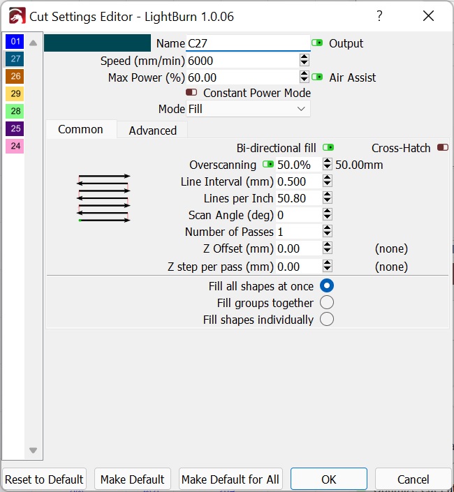
After upgrading the 2.5W laser diode on my machine to one of those Neje 40W modules, I have been “seeing doubles” on my raster scans (fills). Scans with the same controller/firmware/gcode sender/machine/feedrates, using that 2.5W laser were perfect. I’m using GRBLesp32 on a 6-pack, with laser mode enabled, accelerations limited to 127, xy speed limit at 7500, and z speed at 2000. At <=6000mm/min with a diode, having any issues with scan offset seems weird. What makes this rediculous, is the laser is actually turning on too early, without even using scanning offset in lightburn!
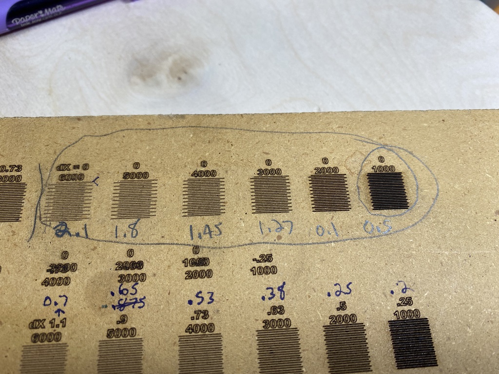
Regardless, I ran some tests on the machine to figure things out. This image shows the laser turning on too early using the default lightburn settings “offsets disabled” (bottom most line is drawn from left to right, alternating as it goes upward on each area):
The numbers above the patterns show feedrate in mm/min, and the Lightburn “Scanning Offset” used for that speed (at 60% power on the 40W module for those interested). The “overscan” setting is maxed out to 50%. At 6000mm/min observing motion it was hard to tell if the gantry was 100% up to speed when the laser went on/off. The other data points I could tell were definitely up to speed based on audible observation.
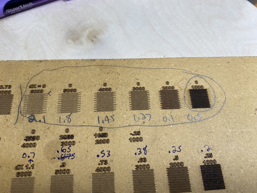
After an about one hour of measurements and test iterations, I was able to come up with a list of feedrates/offsets to produce this seemingly OK test:
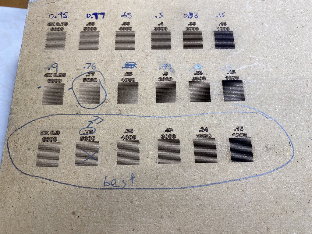
Now, after completing this “scan offset tuning” mission, I was excited to start producing some neat stuff. Unfortunately there are still “doubled up” artifacts on my etches with scan offset enabled and the table filled out with those values! (cuts/lines are OK) This image shows a cube with a doubled “100” on top… at 2000mm/min using the offsets labeled “best” above:

First off, based on how scan offset is supposed to work from all the tutorials I’ve read, with my laser turning on too early the offset should be negative, but it ended up needing positive? Why is lightburn turning on the laser too early to begin with? Any suggestions on how to correct this? It’s hard to believe my controller is predicting the future and doing this… unfortunately verifying start/stop points is very difficult with relative gcode moves (I have no gcode veiwer that can graph that).
I can’t imagine this method of offset would work at all for most hobbyist lasers, since they don’t scan at a constant speed with a decent feedrate. You can’t predict what the planner will do, or what offsets it would need after the planner modifies output. This offset concept only applies if the scan speed is fixed the entire line (so either industrial controller, or very low resolution scan).