Screen grid numbers reversed

This is nearly 1/2" and that should be way more than enough for the go/no-go on the switch actuator.

If it is electronic rather than mechanical, there could be something that is in close proximity to the switch keeping it activated. I am pretty sure those type of switches have 3 wires instead of 2 of them.

Yes Mike, It was a $27=2 so I tried 3,4,5 and then 10 so I could really see it happening. I thought I was simply losing work area until you guy’s mentioned the settling back into 0-0, which is quite interesting.
I mentioned this to SM Support in particular but I still have a gut feeling the issue may be with my setting up of the machine and the enclosure I built.
I was very careful with the wires (flat type) which I think have Three pins (will check today) at the socket.
The Y axis ends are butted up against the enclosure and blocked from movement either side…for rigidity…maybe too rigid or maybe the wires are wrapped too close together..EMI.
Might take it out of enclosure and set it up on its own and loose up the cables to see what happens.

I dug out all the Error codes and basic Gcode terms last night so I might be able to decipher the console reports…also looked at the nuclear option $RST…But only as a last tesort!!

Not sure who said this, but no switch made, mechanical or electronic, has zero hysteresis (difference between open and close).

Anyhow, let us know how your tests work out.

Hi Mike

This is from your post above, regarding the Homing cycle…
“The machine will pull off the switches slowly until the switches open.”
“The machine will reverse back onto the switches very slowly until the switches close.”.

Thats what I meant by setting back to 0-0.

I took the machine out of enclosure and everything looks ok, no snagged cables and checked all connectors…all seems ok.

Im looking at the console report and noticed (G1 Y -79) and realised that is the Height of the rectangle on screen.

Also (Go X -122Y0) on the console, relates to the Width of the rectangle on screen


Does that indicate anything with regard to the ALARM2 on console and the ALARM:2 - Common user error (GRBL error…means…tried to send your laser out of its usable work area…your not using Absolute Coords as yr start from setting.

I was following the wiki instructions for set-up using LB which asked me to use Current position.

Sorry about the phone pics of screen, I was thinking so hard about this…I forgot how to get screen snips onto this msg.

I only use Current Position when using the rotary. ALL other times it is Absolute. Current position is not repeatable but Absolute Position is both repeatable and easily predictable.

Yes, it is possible to go out of bounds with that Y-122 command. With Absolute, there is never a negative motion command because Lightburn works in the first quadrant. Your machine can be confusing because your Home position is the left-rear rather than the left-front. However, if you imagine looking at the graph paper from the bottom instead of the top (flipped over top to bottom), you will see your coordinate system as +X+Y for all moves.

Okay, I thought you meant the $27 parameter was set to zero.

SHFT-WinKey-S pulls the Windows Snippet tool. Frame it, save it, and drag the file into the Reply.

Looks like once you get the limit issue resolved, you will be good to go. Maybe you can send an email to Snapmaker with the URL to this Thread?

Good idea about the URL, Misken also mentioned a G10 command…something like (G10 Lp1 X0 Y-400…or something like that.I have it noted at the workshop, but maybe using that is what allowed me to run the couple of engraves successfully. I also read a post where he helped a snapmaker user deal with a similar issue in the same way..with success.
My module was to the right of home..off the switches, at the time and I must have hit pot luck with the start from or oragin positon, and it worked.

I can try that again tomorrow if tech-team hasn’t replied by then. As for now I best get off to the St Patrick’s day parade…or there’ll be talk in the village!
Its still very cold here so I think a high stool by the fire should be the best vantage point!
Also see Central University Florida turned up for the Dublin parade…400 members is a lot of brass!

Thanks Mike

1 Like

When Melvin mentions, pay attention. He is very good at this stuff. Just remember, one change at a time. If it does not fix something, change it back and move on to the next item.

Yeah, the UCF story was a big deal here too. :grin:

I hate it when I get lucky, but then the luck runs out. That lures you into a false sense that it really ain’t broke.

Enjoy the parade. We cad do this stuff later. Oddly enough it is cold here too, at least cold for Florida. :joy:

Don’t think this is entirely true.


When we look at our project in Lightburn, we see only 1 of the possible 4 quadrants.

The only reason we need to deal with an origin is to determine which quadrant the machine operates within.

This is the coordinate system. For any of these, the origin is 0, 0 – switches or no switches.

What corner the machine homes determines it’s operational quadrant.

Mine homes to the rear/left, so my machine operates within quadrant IV

Front/left quadrant I

For Lightburn or any other application to generate the correct code, it needs to know the machines origin (that specifies the quadrant) as selected in the device settings.

Mine is in quadrant IV and shows what happens to graphics when moved to adjacent quadrants. Any image or vector is mirrored across the axes. In case you forgot, quadrant I is top right and it follow counter clockwise, II, III and IV.


Just because a vendor set it up to home in a particular location doesn’t mean you can’t change it, you can clearly change it or all of these would home in the same place. How much work you want to go through to change it may be in question.

Not all Ruida home in the back left… any controller worth it’s salt is configurable to any quadrant. It can be a frustrating endeavour to change it, as I’ve know a couple that have changed the machines origin.

As @MikeyH advised, for all practical purposes, use it as it’s configured, saves a lot of hair pulling and I don’t think it buys you anything. Just MHO.

:smiley_cat:

1 Like

We could talk Coordinates all day. What I said was based on the fact that his X and Y scales in the workspace were both positive.

My intention was to give him a mental picture of what was happening on HIS diode machine.

I do not think I was wrong when I said Lightburn expects to operate in the +X+Y quadrant. @LightBurn can correct me if I am wrong and I will quit saying it. I do know new users seem to grasp the system easier if all moves are absolute and positive.

I was a CNC Technician and used to fight with engineers that preferred G91. The machinists would not catch program errors, the worst one being a 2" boring bar snapped off in a lathe with a 60hp spindle.

I do not dispute what you said for the most part, I was hoping to keep it simple.

We are used to the coordinate system going negative as we pass the 0, 0 point, either left or down. Once a controller knows which quadrant it’s operating within, there is no need for negative number.

For example, it does not need negative numbers to deal with quadrant III as it’s only one quadrant. Left so many steps or down so many steps… no reason to carry a sign when it can’t go negative.

The only way to go negative is to leave the quadrant, which it won’t let you run.


I don’t know how Lightburn handles these, I remember them saying it’s all positive numbers and then reading it has changed to floating point numbers. Don’t know if that was for the milling machine application or not.

However, it doesn’t matter which quadrant, they can all be handled without using negative numbers since we’re only dealing with a single quadrant.

Make sense?

:smiley_cat:

It does to me, but I am not the original OP. :joy:

It’s somewhat interesting that when I saw Jack’s IV quadrant graph I got the concept as quickly as the 1 quadrant graph with all positives…although my brain assumed II quadrant to be aplicable…but only because of the Homing (back-left) with my machine…An auto assumption.

There was one thing I noticed about the ‘fisherman in the boat’ and that is its mirror III quadrant. In that quadrant the writing was reversed and in my image of the woman on the Indian Vtwin…the word Indian is also reversed…Is that significant?

I did a lot of study last night, into Error codes and G10 using +/- values and put some time into it today.


But kept getting Error2 and others, but speaking of other quadrants..I noticed above the 0 on Y axis Left side of grid, there is a -40 and the same -40 at opposite on the right side of the screen grid…hope it shows in that pic as I left the laptop as may return to it later.

l

Today I decided to input $RST=$

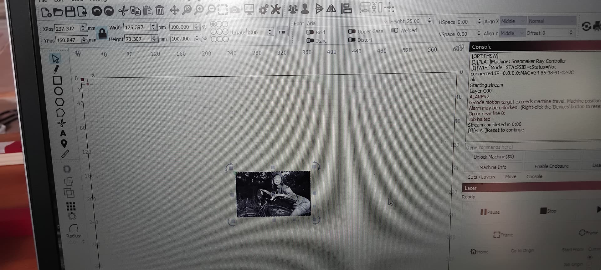
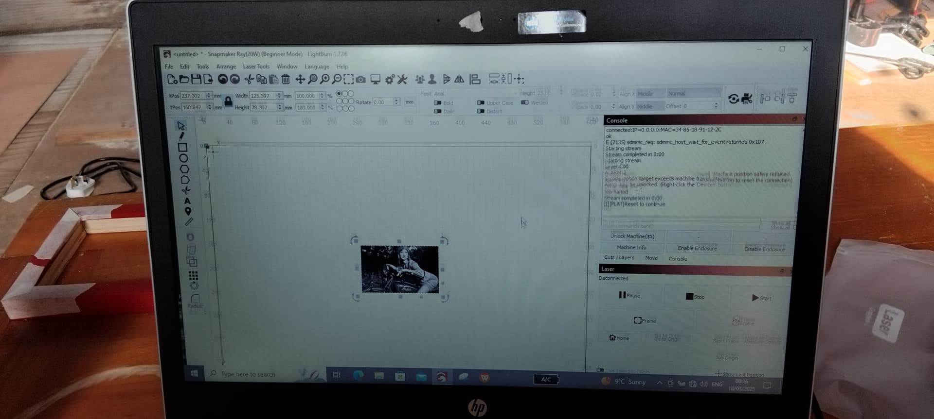
On screen, X Pos 300 & Y Pos 200 and the image I used was in the centre of the screen.

Job Origin set to top left circle.

Move Window, Get Pos = X 300 & Y 210
Move To Pos = X300 Y200

Laser Window-Start From = Current Pos.

I pressed START & module moved to front Right, and crashed into Y axis near front corner with Motor Judder…Pressed STOP.

In the Move Window, Jogged Forward ( chevron pointing down) and Gantry moved toward Back of machine.

Move button (Left pointing chevron) moves module to Left & Right pointing chevron moves module Right.

Move Pos set to X300 & Y 200..Pressed GO.
Module moved forward & Right..Juddered on Right hand Y axis.

I input to MOVE Pos, X0.00 & Y0.00…Pressed start…Moved a little bit…And began lasering.

I adjusted Power & Speed during engrave and job completed.

Because it was well out of focus, I discovered the laser dot is Narrow on X and long on the Y.

Gantry moved toward front during engrave.

The image was engraved Upside down.


Sorry, lost conection!

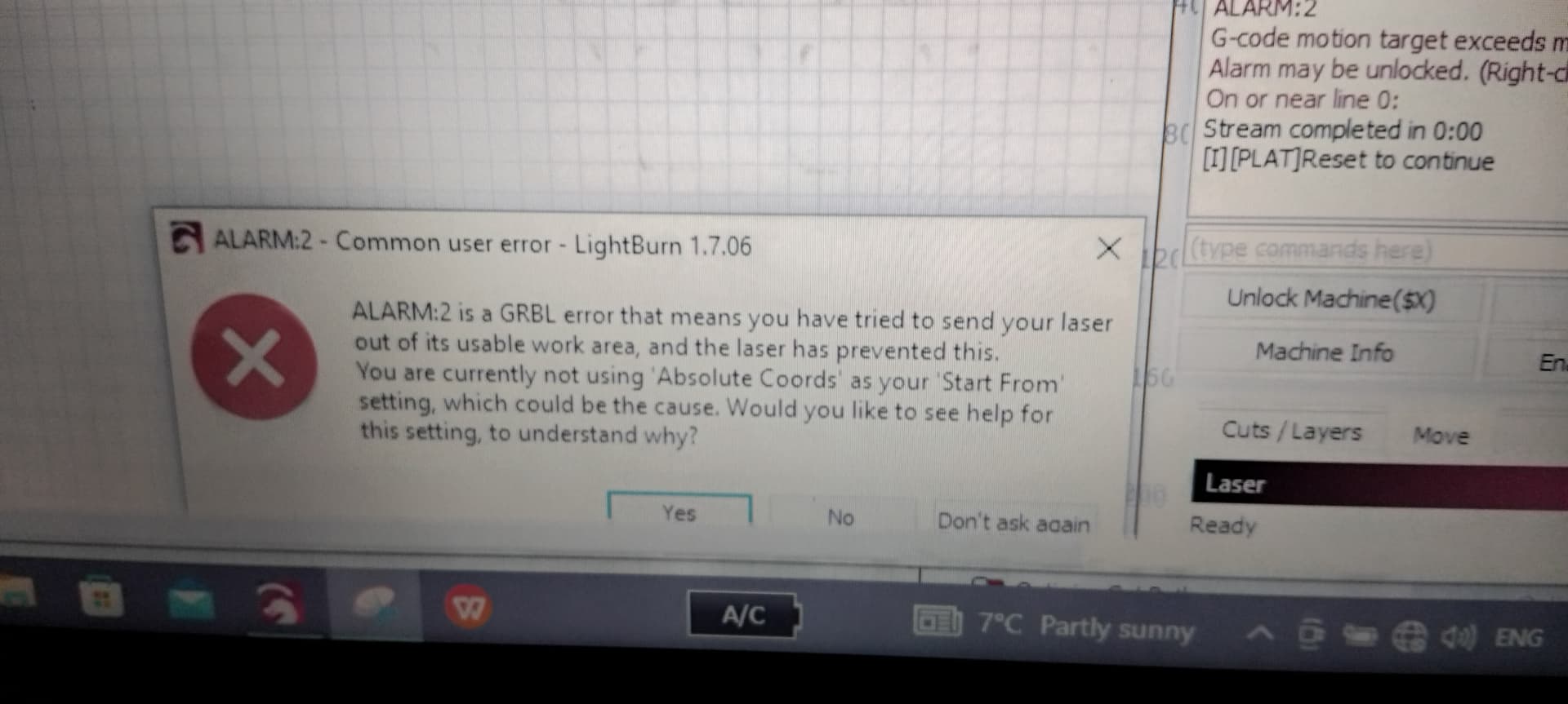
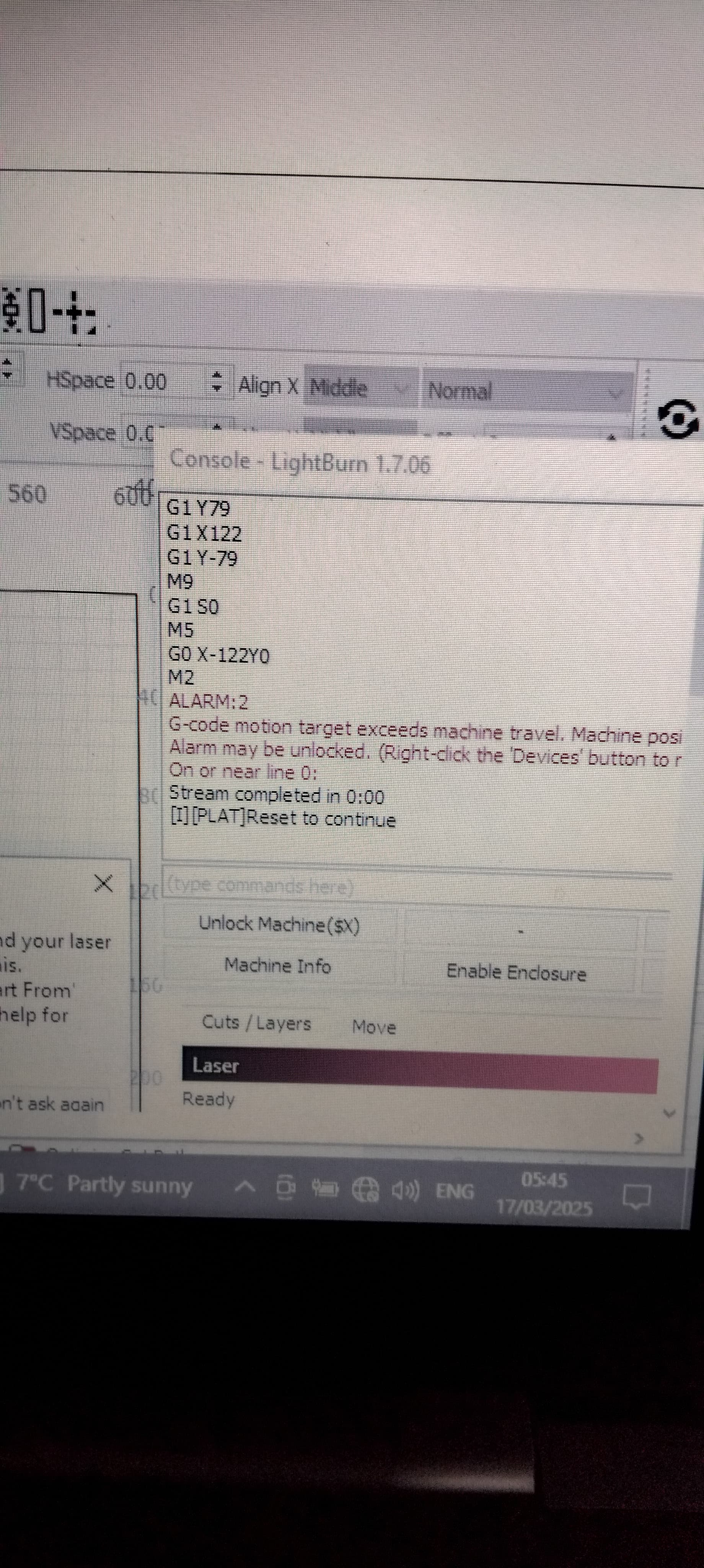
Does this info say anything about the coordinates of the control board and those of Lightburn.

No reply from Snapmaker as yet so no info on limit switches & Homing.

This topic was automatically closed 30 days after the last reply. New replies are no longer allowed.