can any one tell me the difference between MKS-DLC32-KL-V1.0 and XY-DLC-32-KL-V1.0 (2.1)…
Looking at Connection Air Assist to the S9…
Without having to wire in/up relay’s and such…
On the Sculpfun website a new motherboard with Airpump and controller is 159$…
Trying to locate all pieces separately…
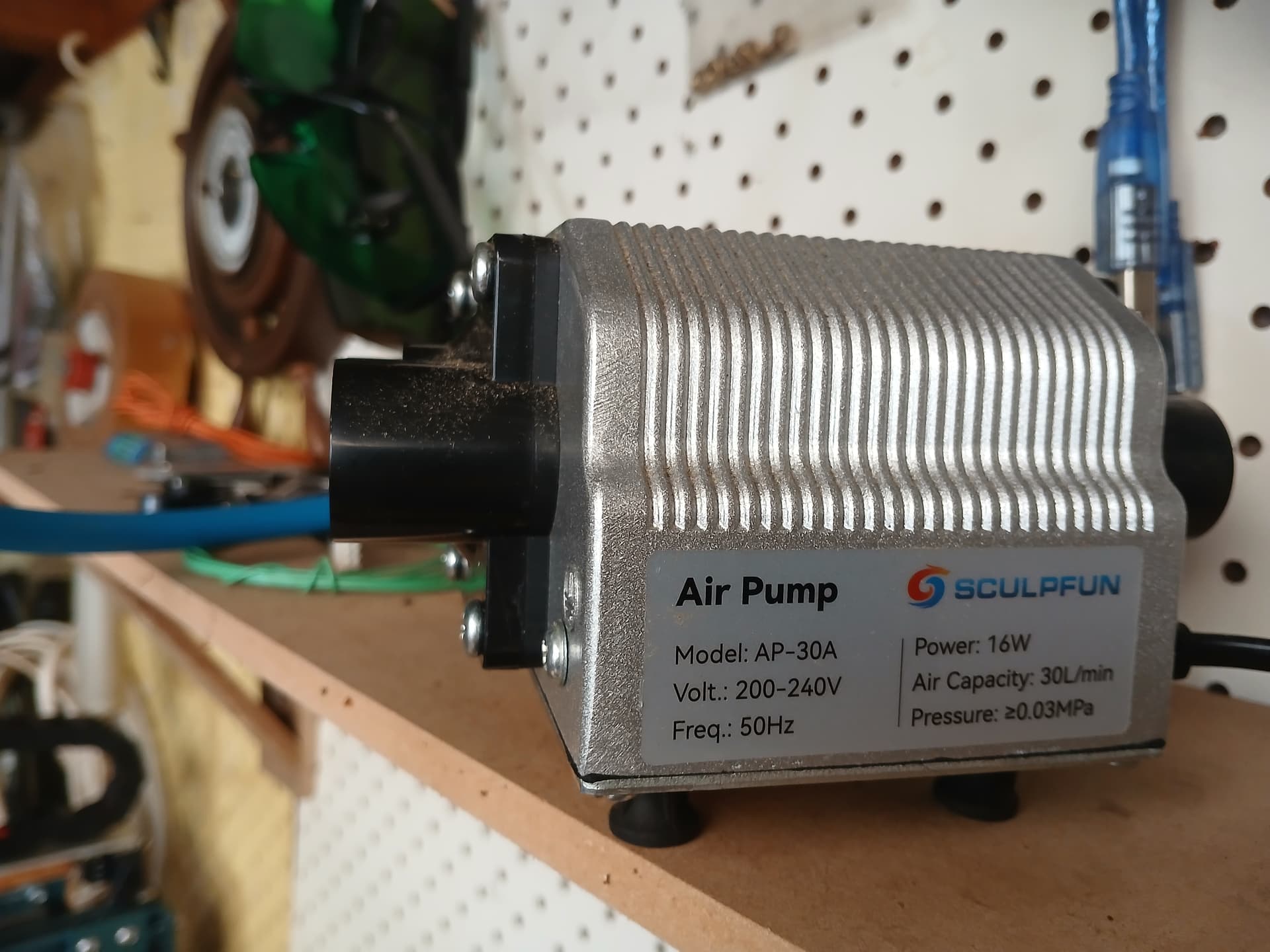
Do you have an air assist pump that directly runs with 12V? Otherwise, you will need a relay anyway.
The MKS mainboards do not have a dedicated air assist port that can drive the pump, you need to choose one of the Sculpfun boards. All newer boards they supply have this port. But I think the XY-DLC32 is one of the first generations, it hasn’t got this port.
Here are some screenshots, maybe you can show some of the ones you are talking about.
Melvin, I have read the wiki you posted… my problem is with the wiring of electronics, house wiring is ok…
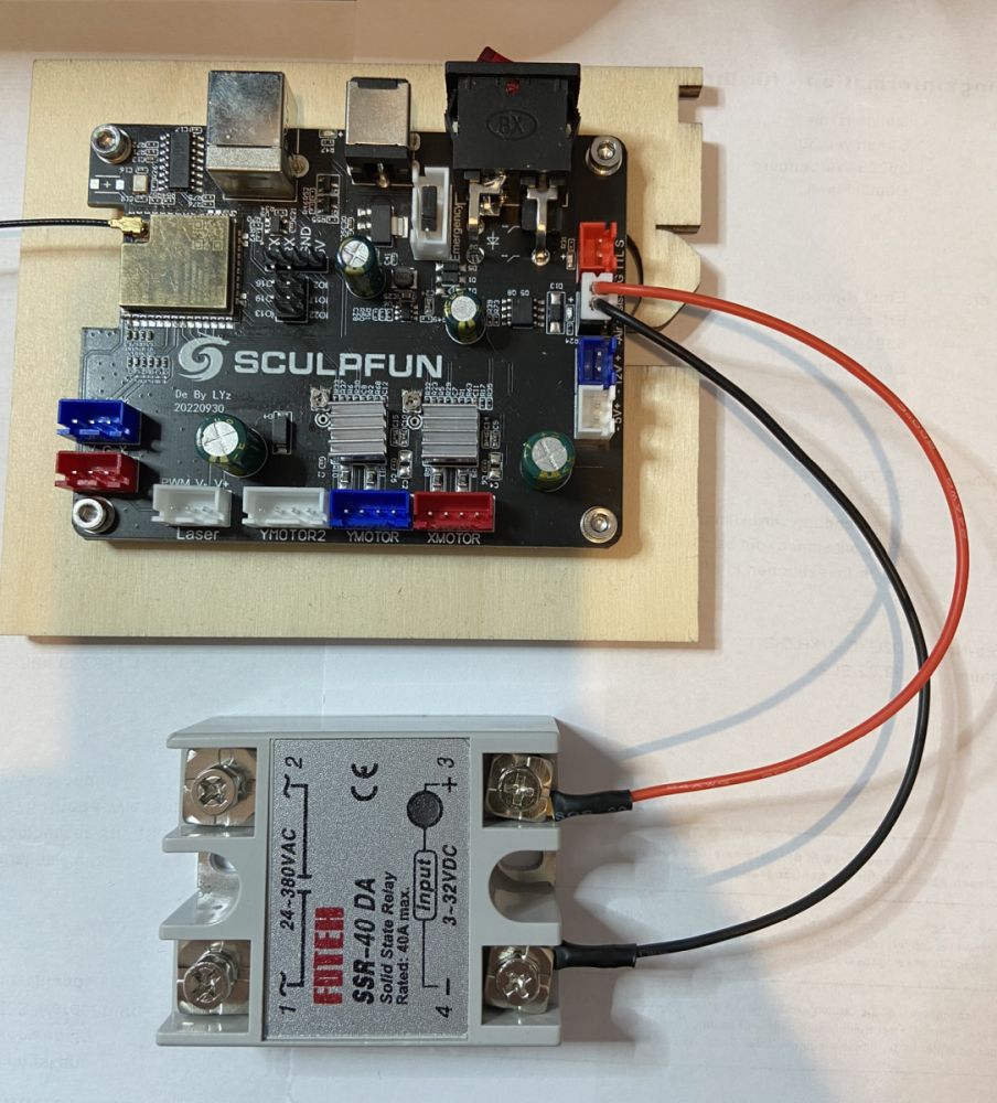
I post picture’s of my pump, and a couple relay’s I have, are these relay’s ok…
My problem is the wiring between the pump and relay the picture in your wiki looks like it comes from below the power plug but I did see somewhere that it can come from the pump itself…
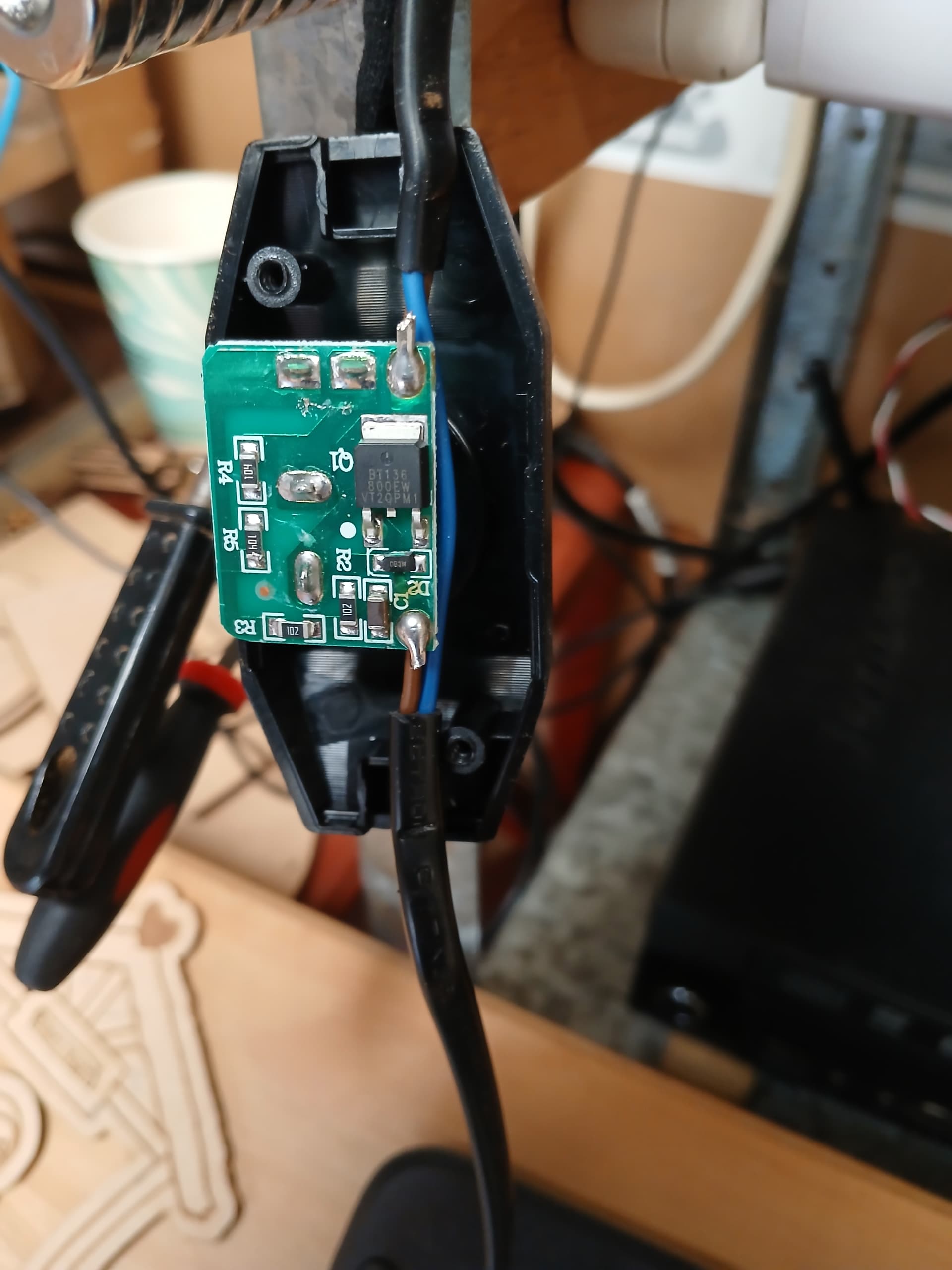
Can LB run the pump switch which is variable (low to high)…
The Sculpfun website shows the air assist kit at 149.99$ (280$ NZ)… a bit expensive… Which is why I was looking at other mother boards…
If there is any way you could draw me a wiring diagram that I can understand…
The left relay can’t be used, it’s 12V. You need a 5V relay, that the board can drive. On the other one, it’s written on the side, I think.
Regarding circuitry, you wire the relay in the path of one of the wires. In your case, I’d select the blue one. Cut the wire and put both ends into the relay. The relay will then open and close this cable/connection then.
But maybe there’s someone around that can have a look at the setup? Because it’s not good messing around with those high-power wires if there is any doubt how it should work.
Melvin thanks for your help I been in hospital again, gotta learn to take it easy…
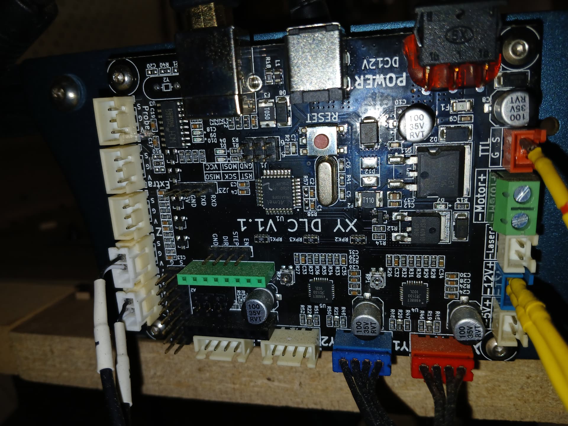
Just to clarify If I use the board I have (XY DLC V1.1) It has no Air Assist plug on it so I can’t use that one, or do I use the tha Relay the one on the right as picture above… or do I get (Sculpfun Motherboard | 32bit for S9/S10 /S30 series | Laser Engraving) do I still need a relay…
Hell I hope I am explaining this ok am attaching a drawing of the relay and what I’m guessing is the correct way to wire this up…
Cheers Merlin…
Yes, you do. The newer boards control the pump directly, not using a switch. If you have a mains powered pump, you need a relay in any case.
This would look like this:
Hello Melvin, just reporting that I have the pump and relay wired in, I did use the Blue as suggested but that did not work, as the Red wire is the live wire that did work, but some problems… When the Air Assist is set for off, the pump is on, when it switches to the next layer which is set for on the pump turns off…
I tried switching the A3 wire to CH1 but the pump just does not work at all…
So something is off somewhere, as per the lbrn2 diagram from above, the wires are attached as VCC to DC+…GRN to DC-…A3 to CH1…
As my mainboard is V1.1 but all looks the same as V1, but wood it make any difference which Ground pin I used…
Did you use the right (SSR) relay from your pictures above? This is then caused by the relay being “low-level active”, which is inverted to the air assist logic. You need a “high-level active” relay. This also holds for the other type of relay. For the blue relay type, you can use different contacts to invert those again, but this would turn the pump on every time the laser is turned off. So not a very good solution. Check if you have a high-level active relay somewhere.
Sorry Melvin I’m very confused now, can you point me in the right direction on where to purchase said Relay, I have attached the Mainboard I have and the only relay’s I have on hand are the ones above under the pump picture…
Sorry but I don’t know very much about electronics…
I picture of the relay is worth a thousand words..
Thanks again for all you do on here for us that know bugger all…