I have a Chinese galvo fiber laser that came with a BJJCZ controller and a stepper motor 4th axis. I have a home switch on the 4th axis which is just a inductive sensor that picks up the head of a bolt.
I am using the 4th axis to make 4 sides of a square part and I have a fixture plate attached to the 4th axis to hold my part. So I need to jog the axis manually while I run an indicator back and forth across my part, then say “it’s level… this is zero”.
How do I do that in Lightburn? Or is it even possible?
If you can run it from EZCad2, it might be possible.
From what I know, besides the X and Y axes, the rotary is the only port that’s supported. They don’t support a Z axes for adjusting height while the job is running.
Maybe @Rick can answer you question with more information.
Jack is correct, LightBurn does not currently control the Z axis on a galvo.
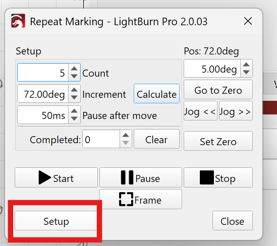
The rotary axis can however, be used as an indexing table with the Repeat Marking feature
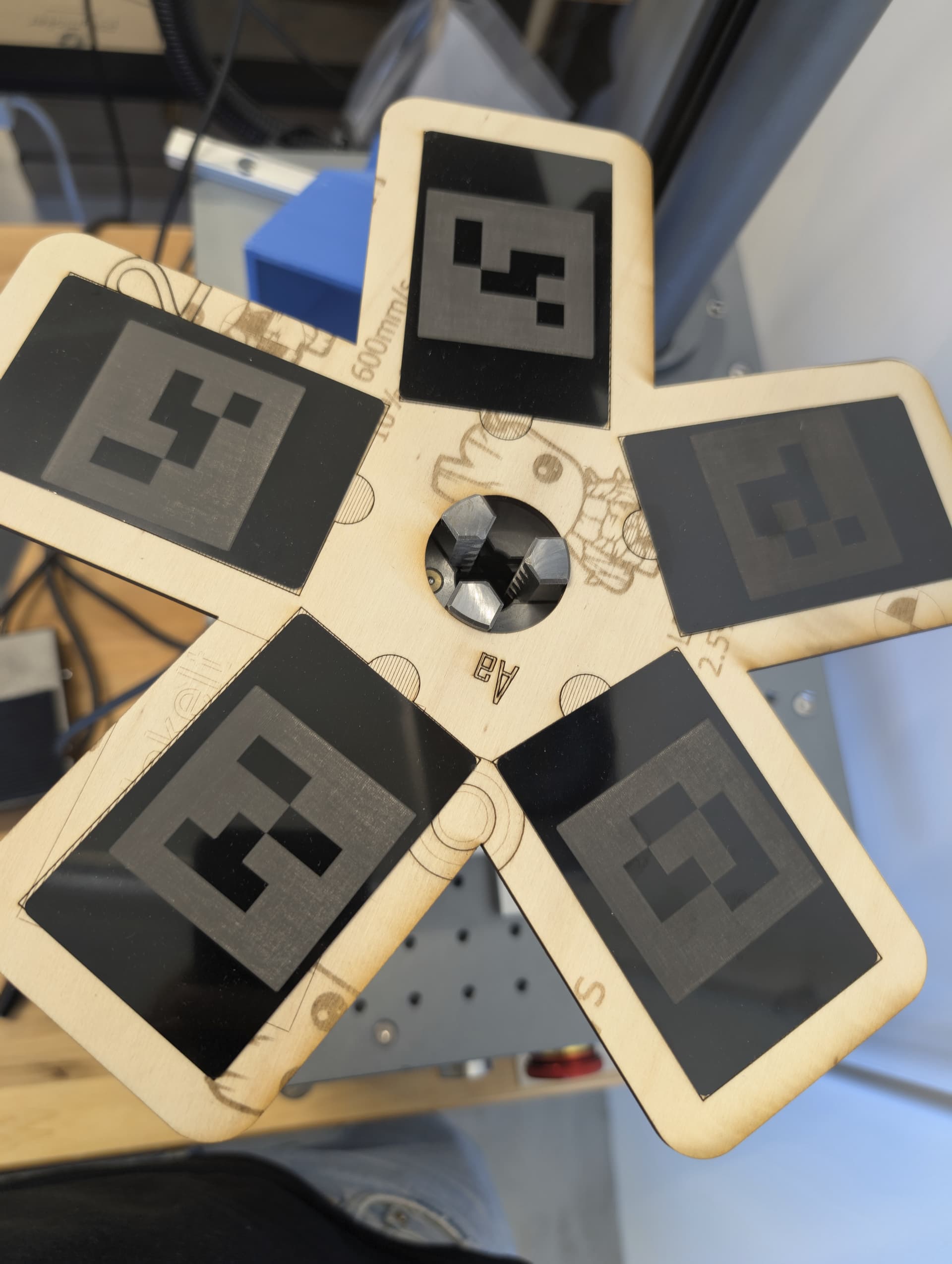
Let us know if that brings you closer to what you aim to do, and feel free to explain in more detail. Pictures of your setup could help us understand better.
There is a misunderstanding on what I am trying to do.
The Z axis is irrelevant.
Let’s say I have a square part that I want to engrave on all 4 sides of. I mount it in the chuck of my 4th axis rotary. How do I ensure the flat side is perfectly flat to the plane of the laser?
The way this is done in a manufacturing environment is you mount the part and then run a dial indicator back and forth across the part as you rotate it using the 4th axis until you are reading zero across the part (or as close as possible).
Then you would mark one side, rotate 90-deg, mark the 2nd side, rotate 90-deg, etc, etc.
Let’s say each step of my motor translates to 0.001 degrees of rotation. How, in Lightburn, do I have the first of the 4 sides mark at 0.010 degrees (for example) instead of 0 degrees?
The way (it seems) Lightburn works would be fine for arbitrary marking where rotational position doesn’t matter - like on a cup or whatever. But if you have existing features that you need to correlate with (like the flat side of a part, or existing holes or whatever), then you need to be able to adjust the zero offset (rotationally) of the marking.
If the theta axis of the indexer is just X or Y, then is it just a matter of using absolute coordinates and offsetting the start of the part by a linear amount in Lightburn?
It would be nice if there was just a “jog indexer by 1 step” button - that would let me do what I need. Ideally with a 1/10/1000 step selector switch so I can dial it in and then that becomes “theta zero” for the subsequent marking.
The way I understand it, Repeat Marking does exactly what you are looking for. Admittedly, I haven’t used the function myself in a real project yet.
I sent the link in my previous message. Not sure if you saw that?
You answered this question here:
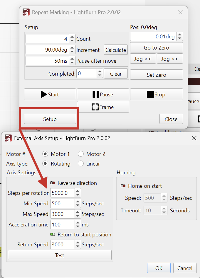
LightBurn will calculate the motor steps to degrees when you enter the “Steps per rotation” in the Repeat Marking setup:
Use the Jog buttons in that window to level your first side and “Set Zero”. (I see the smallest possible Jog step is 0.01deg, but that should be precise enough.)
I reckon most people would be more comfortable with using degrees of rotation instead of motor steps. Please let us know, if you find having a smaller Jog step than 0.01deg would be beneficial.
Please let us know, if this helps.
Next time I use the Galvo, I’ll evaluate my instructions here!
Thanks for the reply - now I see the disconnect on my side.
I did look at the repeat marking, but it looks like I can only mark the same thing on all 4 sides. In this case I have a customer who wants me to mark a bar code on each side. The barcodes literally say “SIDE A”, “SIDE B”, etc. This is for use in an industrial robot where cameras will read the barcodes as the part I am laser marking is in use.
I don’t think I can mark somethign different on each side with repeat marking from what I see. What I did before was use splits and the layout in Lightburn to get the rotation I wanted… but there is no way to set a zero offset that I could see.
I realize I am trying to use Lightburn for more industrial purposes than you likely intend it to be used for, but there is a huge untapped marked out there for industrial lasers. Most of the OEM’s have their own software and it’s really bad. If you ever flesh out the automation interfaces in Lightburn (or develop a fleshed out API) you could really clean up on becoming the standard for industrial laser marking.
We have 4 lasers at work, 3 of them run Lightburn and we’re trying to standardize on this software going forward, so I’m trying to come up with work-arounds for the limitations we currently face (like the different marks on 4 sides thing).
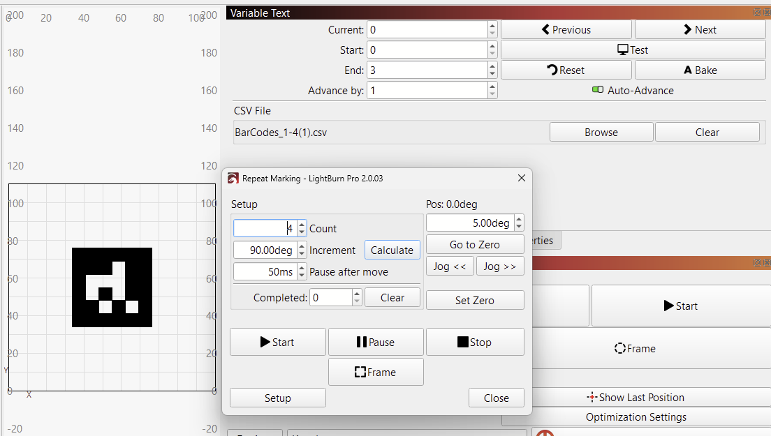
Variable Text can be used together with Repeat Marking to engrave different text with each step.
It’s not currently possible to load images, or barcodes this way.
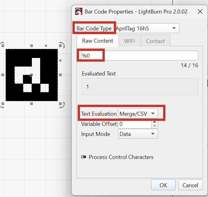
But the Barcode Tool can read text input from Variable Text.
Are you using AprilTags or ArUco markers? - The Bar Code Tool supports these.
My suggestion is as follows (I haven’t tried it myself on the Galvo, but should work):
Create a CSV file with the desired barcode values, each on a separate line. Or use this one: BarCodes_1-4.csv (12 Bytes)
Go to “Window > Variable Text”
Enable Auto-Advance and click on Browse to select the CSV.
That is awesome - I didn’t even consider doing it this way but assuming it works it will solve my immediate need.
We wrapped up the last job just indexing the part manually and it’s a few weeks before the next parts are due, so it will be a little while before I have an opportunity to try this out but I wanted to thank you for the time and interest in this particular challenge.
I mentioned we’re trying to get away from various proprietary lasers and standardize on Lightburn… if you guys ever do flesh out an API, that will open up a world of possibilities because I can do lots of stuff (X/Y position motion) externally from lightburn and then just programmatically fire off the laser to do what I need.
Anyway, your solution above should work with what I need for now and I am excited about future features you have coming - it’s only going to get better for us
That’s great to hear, and we like to support you in these steps. You’ll definitely hear it when there’s news about an API.
Feel free to send an email to support@lightburnsoftware.com with your specific wishes and requirements. Mention this thread, and I’ll make sure your feedback is considered.