Hello, I am looking to build my xy-table myself too.
Where did you get your linear axis from?
I was wondering buying these.
1 from 400mm and 1 from 700mm long.
Would the mobile table be to small for the weight.
I see you have a much wider piece.
And where would you get the top working area of the table?
Hello
I think you are right, not enough spread. Pretty close though, a lot easier then all the spacers and angle I needed to fab up to match heights. I sourced from all over mostly AliExpress but since then I found a couple better places. How much usable travel do you want on the X axis? I have a 300mm spread and a 1000mm screw on the X so I have 700mm usable travel. Drawing one up right now X only table that will have 1200mm usable travel.
Something else to consider, really want 20mm lead screws I had started with 1605’s and replaced them with 1620’s, even with the 20s it takes 192000 (not a typo, 192 thousand) microsteps to move 600mm with microstep driver set to 6400, which is what my driver in the laser is set for. The CNC controller I built for it to run it independent I have the mocrostep drivers set for 320.
If you want to purchase a few components and bolt it together search Ali, If you want to get into it deeper, spacers, angles etc and really build it like I did Limo Bearing has most of the parts for really good prices and has the long stuff way better pricing then Ali. I have some sketches but they are PDF and I can’t upload here, if you PM me your email I’ll send them over, might help.
Hello,
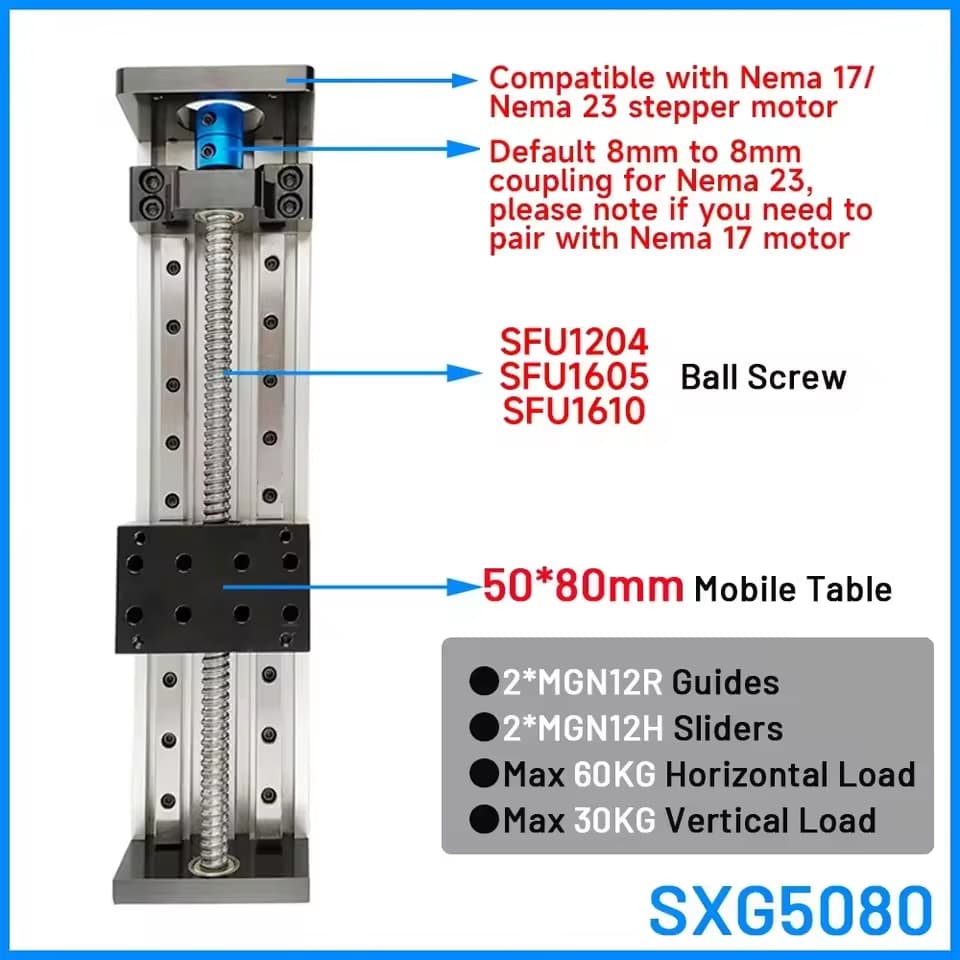
There is also a version with a 100x80mm mobile table, so maybe that would be better.
The ball bearings are 1605 or 1610.
But it does not have to go very fast.
My driver is set to 12800 microsteps, so it would be the same amount of time if to travel a distance if I’m correct.
I was thinking about a travel distance of minimum 700mm.
I would like to use my 100mm lens, so that would be a working area of 800mm.
I think of buying everything on Aliexpress.
But the Limo Bearing site is indeed nice.
But I am from Belgium, so would need to search a website/store here.
some other idea’s.
I was thinking to put the x axis (the long one) on the bottom with the y axis on top.
So there is very much less momentum on the setup to bend the whole thing.
And I was thinking about using T-slot aluminium rails to make the working area of the table.
And I was also thinking, like my rotary, I could connect the x axis as a rotary.
I only need the y axis when I want to make big pieces and was thinking about engraving a slice of 100mm high and the full lenght, move the table and design in lightburn 100mm and engrave the other slice of 100mm.
Or was it easy to implement the connection form the DDCS V3.1 with Lightburn?
I think you are backwards.
If your microstep driver in the laser is set for 12800, and you have a 10mm lead screw, it takes 12800 microsteps to travel 10mm. I have 6400 setting and a 20mm lead, so 12800 microsteps will travel 40mm for me. You will be sending 896,000 microsteps to travel 700mm. I would send 224,000. I don’t know what the max speed the board in your laser can send steps to the microstep driver, but I know with my Uno 2000/sec is about max. And it was bad when I exceeded that.
Might be a good idea. Might not. It’s a tradeoff.
I went the other way because I didn’t want the cabling traveling so much and I didn’t want the Y motor (Sticking out) moving all over the place. With the X on top, the X motor only moves back and fourth the distance of the Y travel, which can’t be more then about 300mm or it runs into the tower. Motor and cabling way off to the end out of the way. Put the Y on top, the Y motor and cabling moves 700mm back and fourth, sticking out the front, (if it stuck out the back it would collide with the tower). If you look at bench mills, the X is always on top of the Y and they are pretty beefy.
90% of my work is done that way. You could really just build an X table, save the additional expense and not be missing much.
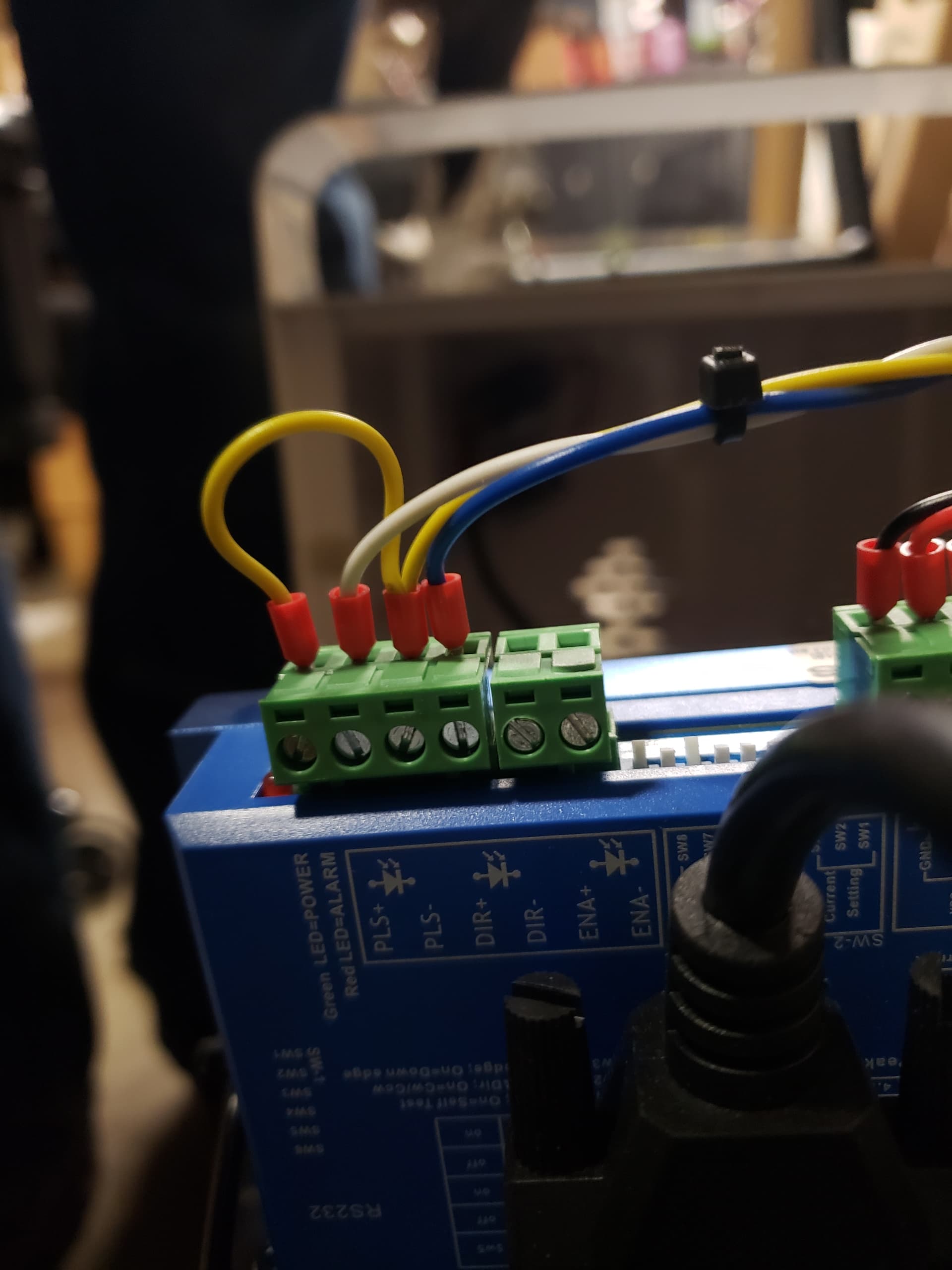
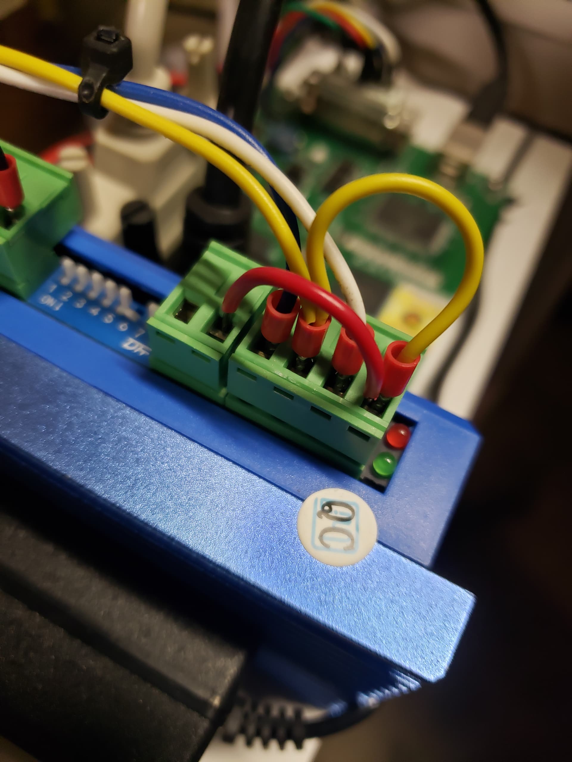
Something else to consider, X Axis runs great off the rotary output, BUT, it WILL run off the end if you are not careful. Probably even if you are careful. When running table off the CNC controller you have home switch, soft limits. No such features on the laser’s rotary output. I added additional NO limits at each end, connected to ENA and 5VCC so microstep driver goes into neutral if limit is contacted.
What I did was start small, built a small single axis to start with, prototype. Then built a 2 axis controller so I could control the Z drive and the X. Then I built the XY table and an XYZ controller.
Baby steps.

Limit SW wiring
Don’t skimp on the heat shrink tubing and quality shielded cabling.


Don’t forget one of these!
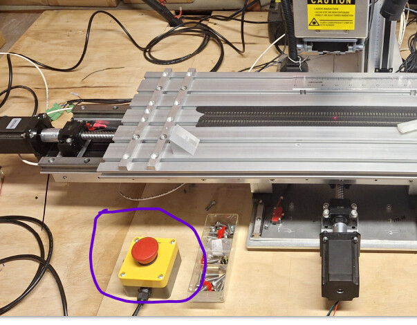
You’re totally right ![]() my bad
my bad
Had not thought about the cabling indeed. Just the stability. Thanks for the heads up.
With the limit switches on the ENA you are indeed already quit protected.
Indeed I do think I want to do too much in one go.
It is a side hustle for me and don’t want to “waste” money ![]()
But thank you verry much with all the tis and info!!
greatly appreciated
Just a hobby for me as well, I like building things almost as good as what I could go out and buy for cheaper. ![]() ,
,
I’d suggest just going out and buying a Maxce IndexX table for someone that didn’t like tinker. Pretty nice table.