Omtech 60W cutting jigsaw puzzle
Anyone who has used the 76.2mm Focal Length lens:
I done a ramp test with the ramp raised 3 1/2" at one end of course.
My best cut line is a good 1 1/2" long, I used the center of that for my distance from nozzle end to material, 46.5mm.
With that setting I tried cutting 5mm ply plus a photo glued to one side with photo on bottom. Speed 10, Max and Min. power 27%, 2 passes. I am not getting a full cut through the photo side. Tried Max power at 35% no difference. This is first I have used the 76.2 lens. Seems as though I am missing a setting I should be changing other than making the distance from surface of substrate different than 46mm or 42mm. Actually I chose 42mm to see if there was much difference. No setting I have tried cuts completely.
Any ideas are very welcome. I am trying to eliminate the many trials I done with a 2" lens.
are you sure the beam is making it out of the nozzle? put tape on the end of the nozzle and see if it hits the center. over 4 corners of the bed.
on my 75mm lens I gave up on using a nozzle because of alignment. the purpose of a nozzle is to direct the air flow on to the cut. when you are 46mm away you might do a better job getting air to the cut using some other method.
Are you using the original nozzle with the lens holder? or an extension tube?
Extension tube
I have the tube pushed all the way up
Didn’t think about lowering the tube
Where in the extension did you place your lens and which nozzle do you use?
I don’t think lowering the tube helps anything.
It’s mainly used to extend your Z reach. Maybe for short focus engraving lens.
I have 3 different nozzles
One stubby one that came with the 30.8mm lens, one for compound lens, and an NO3 Cloudray sent with my 50.8mm lens.
I put the 76.2mm lens in the original which may be wrong combination. I done that because i had more physical space for a silicon washer that made my lens seat tighter.
The lens has its fixed place in the extension tube (either reset or threaded insert) and the distance from the upper edge of the lens to the surface of the material to be machined is the focus distance that should fit the selected lens. To get more concentrated air in the incision, the lens must be moved up in the extension tube, afterwards you can move the entire nozzle down, the lens distance to the material must “always” fit your focal length. Be aware that the laser beam can enter through the nozzle opening without hitting the inside of the nozzle.
The device I have temporarily “constructed” gives me a distance from the lower edge of the nozzle to my material of 10.5 mm. This distance suits me fine, it is relatively close but still I can run over my magnets without a head crash.
That’s probably the problem
If you use the short original nozzle (approx. 18mm) then the laser beam will not be focused enough to get through the nozzle hole without losing much of its power. The nozzle must get very hot?
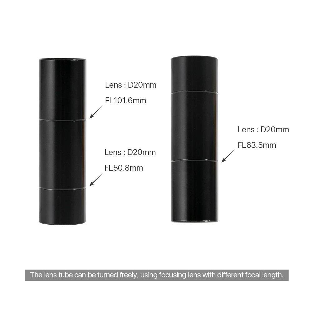
@bernd.dk probably correct here. Here is a selection of lenses and nozzles. You can see the difference between the same lens used to cut and one used to engrave.

Use the nozzle with the biggest hole until you figure out what’s going on.
You can also ‘flip’ the tube over and place the lens at a different distance from the nozzle.
I would think you would see this when you did the ramp test. When it’s not making it through the hole, it’s always been pretty obvious to me.
I had to change my ‘Material Library’ so that the ‘headers’ were 1.5", 2", 4" and compound. All of them have different ‘speeds & feeds’ for same materials.

Okay:
My lens is mounted in the top of the nozzle minus 3 or 4 mm. I understand the measurements to determine FL to substrate.
My lens is 30mm from where the lens is mounted to tip of nozzle.
The lens tube I have threads onto top end of nozzle. I may be able to move lens 2mm away from lower end of nozzle. That certainly wouldn’t be enough to make a difference.
How did you extend the nozzle tip from lens?
I use extension tube (long side) with locking ring and the original nozzle. Overall it gives 62.5mm, 72.2 minus 62.5 is 9.7mm (and not 10.5mm as written before, it is due to measurement error of the lens.)
The downside is that the nozzle hole in the old nozzle is twice as big, but I can not combine the lengths differently and the new, long nozzle with the small hole is of course too long …
I am going to upload three pics if it will let me:
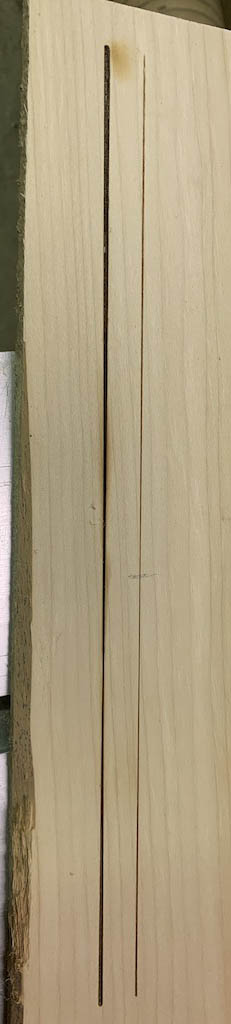
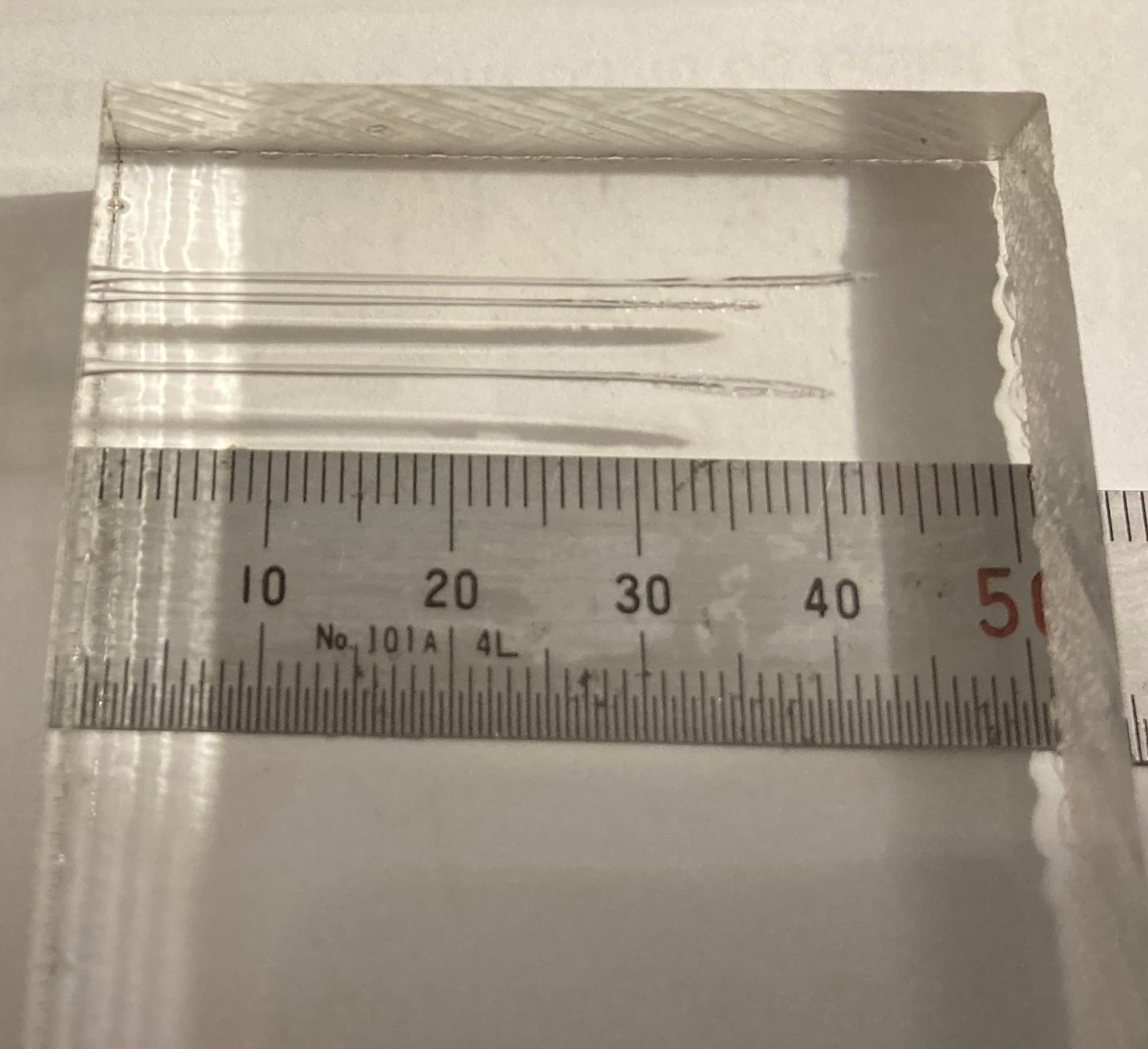
#1 Ramp test done twice, one 46.1mm from nozzle, next was done 45mm from nozzle.
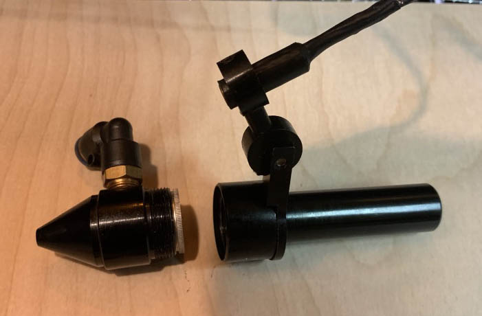
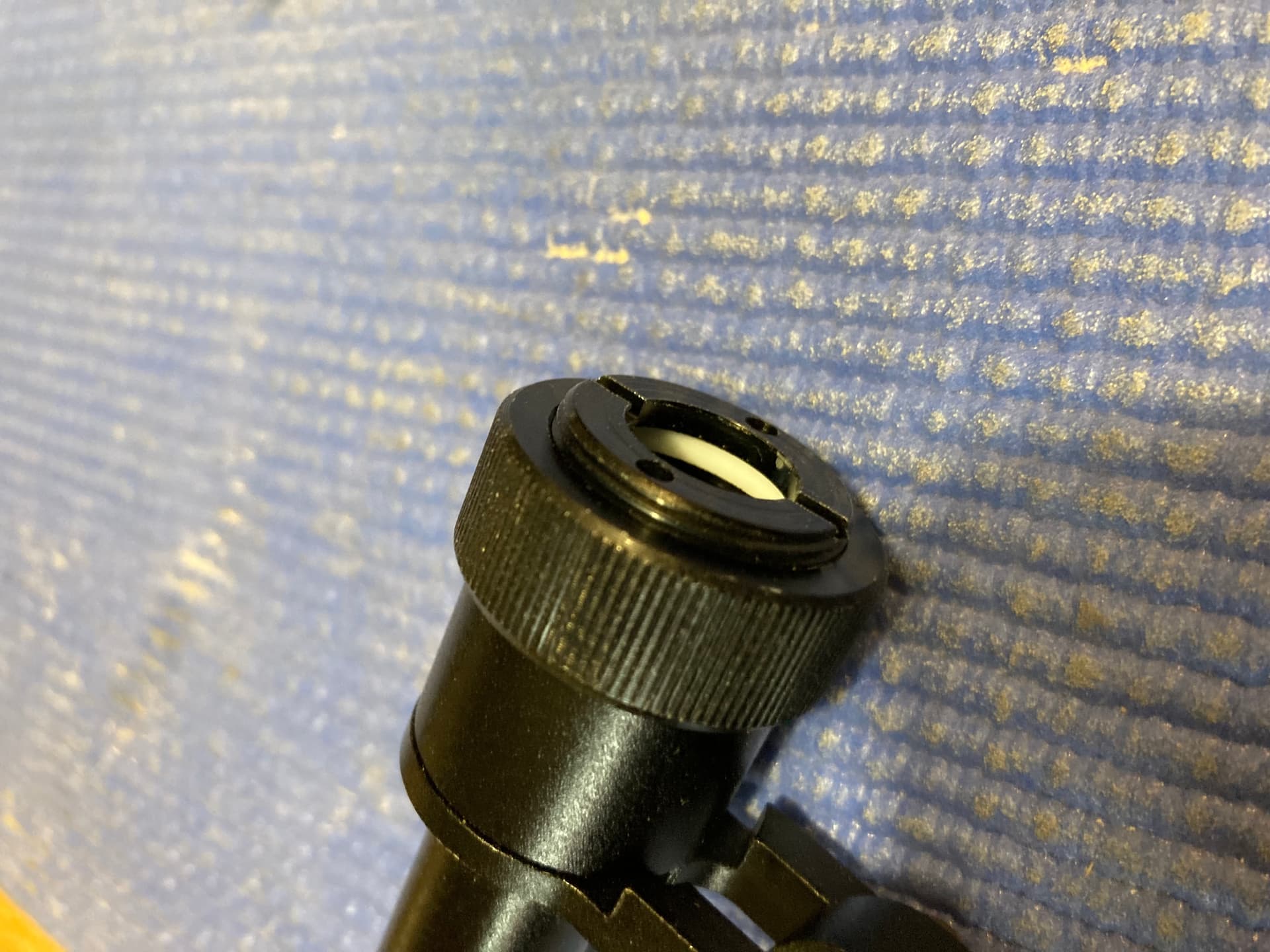
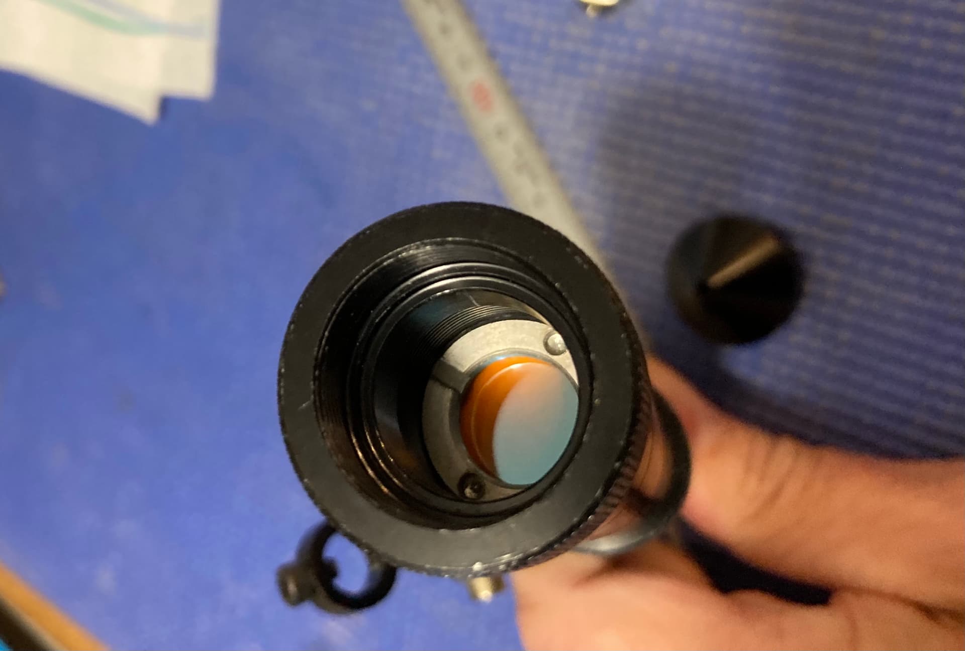
#2 Coupling at top end where lens tube inserts.
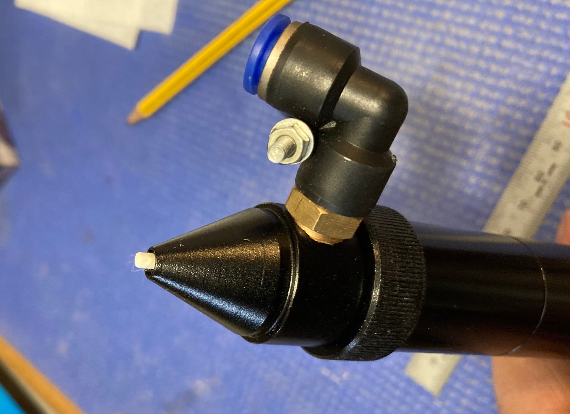
#3 Nozzle presently containing the 76.2mm lens plus the lens tube which is all one piece.
Hole in nozzle is 4mm. Nozzle for combination lens has a hole measuring 6mm.
Is the end of lens tube which has the knurled nut in #2 pic removable?
No, unfortunately it is not and there is also no threaded adapter, I asked Cloudray. But, because I did not want to wait for a new nozzle system, I have made a temporary solution. It’s not perfect nor very pretty but it works ok.
I’m making some pictures tomorrow.
Tomorrow I will do some “serious” 3" tests and report back with my experiences.
Good night
Thank you
Have a good evening
I modified the longest nozzle I have by making the hole 7/32”.
Done a couple more ramp tests. Set distance from nozzle to 40mm.
5mm plywood with photo glued to one side, placed photo side down.
Speed for interior of puzzle = 15mm/sec
Max & Min. power 35%
Perimeter speed 13mm/sec with Max &Min power at 35%
Air assist @ 30psi
Too much smoke residue on topside plywood
Same with photo side
I want to get setting that will give me very little residue. May try a little more air assist. Takes a lot more air with that big hole in nozzle.
My thinking on accommodating the slight changes in the level of the surface of the plywood is to close the distance from nozzle to plywood by no more than half the thickness.
Am I doing that wrong?
I have had a very nice day in the workshop where I have experimented with my 3 "lens. First I will show how to temporarily mount my extension tube on the original nozzle holder.
I have bought some extra threaded pieces which are usually used to hold the lenses in place. It is a bad solution but it is impossible for me to find a threaded piece M22x1 which can be used to assemble the extension tube with the original nozzle holder.
There are only 2 rounds of thread for each part, but for my tests it has been stable enough.

In one of the pictures you can see a cotton swab with a mark which represents the distance from the underside of the lens to the nozzle end.
After that, my distance from the nozzle to the material should be 3.7mm. However, the tests I did have shown that the optimal focus point is 6.2mm. Why there is this difference I do not know and I also do not care, because I stick to the practical results which say 6.2mm.
These tests show focus distance 6.2mm +/- 1mm, the longest penetration is the one with 6.2mm focus distance.
Test1: fokus 6,2mm, 999ms puls, 50% power = 12,5mA 41mm
Test 2 fokus 7,2mm, 999ms puls, 50% power = 12,5mA 36mm
Test 3 fokus 5,2mm, 999ms puls, 50% power = 12,5mA 39mm
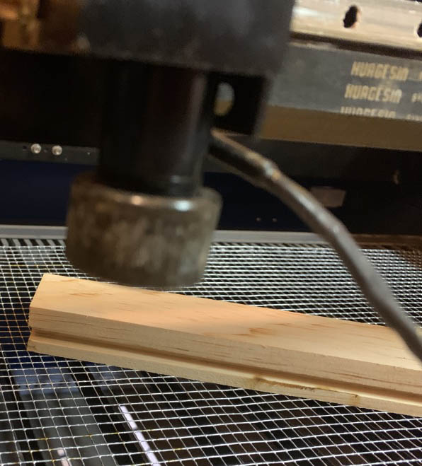
The 3 final tests I did after extensive ramp tests. When it’s hard to find the exact focal point, I use rows of small circles that I set to be cut out with different parameters.
The (vertical) row that has the most clippings has won ;-), it works fine for me.

Although penetration with the 3 “lens is 25% deeper than my 2” lens, I can strangely not find a “significantly” better performance when cutting in wood or acrylic.
Of the materials I have tested today, such as 20-26mm solid pine, 15mm acrylic, 3,4,6mm plywood, there is nothing I could not also handle with my 2 "lens. Unfortunately I do not have very thick foam material in stock, it is this material that I expect a clear difference.
The interval has been 10,20,30,40,50,60,65,70,75,80
(the back row is made with the 3 “lens and the other with my 2” lens)
At 80% I read 19 mA and at 60% it is 14.5mA
Note that from 60% up, not much more happens. It’s pretty much the same picture as with my 50 (40) Watt tube, however, it went up to 70% before the curve gets flat. This is very interesting and also confirms my theory that speed has a greater influence in the high power areas as in the lower ones, which means that the effect of 10% speed reduction is greater than 10% more power.
Finally a few pictures from the tests today, in one picture there are clear signs of sabotage 
I don’t know if this means much, but I usually try to dial a cut in where, using a tissue to wipe the cut, I have the least amount of soot.
Yours look pretty clean…