Severe Horizontal Banding on Galvo Rotary (OMTech 60W JPT MOPA + LightBurn) – Looking for Ideas

I’ve spent the better part of two days trying to track down severe horizontal banding when engraving black powder-coated YETI tumblers with my new fiber laser. At this point I feel like I’ve isolated most of the variables, but I’m hoping someone with more JCZ/LightBurn rotary experience can point me in the right direction.

Machine:

  • OMTech 60W JPT MOPA Autofocus Fiber
  • JCZ USB-Lite controller
  • LightBurn Pro 2.1.03
  • 150mm lens
  • OMTech 3-jaw chuck rotary
  • Rotary connected as Y-axis
  • 6400 steps/revolution

The controller was replaced under warranty by OMTech after intermittent USB disconnect issues. The replacement board has been stable.

Material:
Black powder-coated 20oz YETI tumbler.

Goal is complete powder coat removal exposing clean stainless.

Rotary Settings:

  • Chuck rotary
  • Y-axis
  • 6400 steps/revolution
  • Object diameter: 87.79 mm
  • Circumference: 275.8 mm

I’ve tested multiple combinations of:

Split Size:

  • 0.025 mm
  • 0.050 mm
  • 0.100 mm
  • 0.500 mm

Overlap:

  • 0.000 mm
  • 0.020 mm
  • 0.025 mm

Motor Speeds:

  • Max 3000 pps / 100 ms acceleration
  • Max 1500 pps / 250 ms acceleration

No significant improvement.

Laser Parameters Tested:

Speed:

  • 750 mm/s
  • 1000 mm/s
  • 1200 mm/s

Power:

  • 17%
  • 18%
  • 19%
  • 20%
  • 21%
  • 22%
  • 23%
  • 25%
  • 30%

Frequency:

  • 100 kHz

Pulse Width:

  • 200 ns

Line Interval:

  • 0.020 mm
  • 0.023 mm
  • 0.025 mm
  • 0.030 mm
  • 0.050 mm

Passes:

  • 1
  • 2
  • 3

Scan Angles:

  • 45°
  • 180°

Interestingly, 45° produced a noticeably smoother finish and looked like the laser was gliding across the surface instead of producing distinct raster lines, but the banding still remained.

I also tested perfect focus versus slight positive defocus. Defocusing slightly improved the finish but did not eliminate the problem.

Things I’ve Learned:

  1. Flat engraving looks excellent.

Using essentially the same settings on flat powder-coated steel produces a very smooth finish with virtually no banding. That makes me think the laser source, optics, and galvos are working correctly.

  1. Changing split size changes the appearance of the artifact.

At 0.500 mm split size the banding became much wider, making me suspect the split boundaries might be involved.

  1. Small engravings look much better.

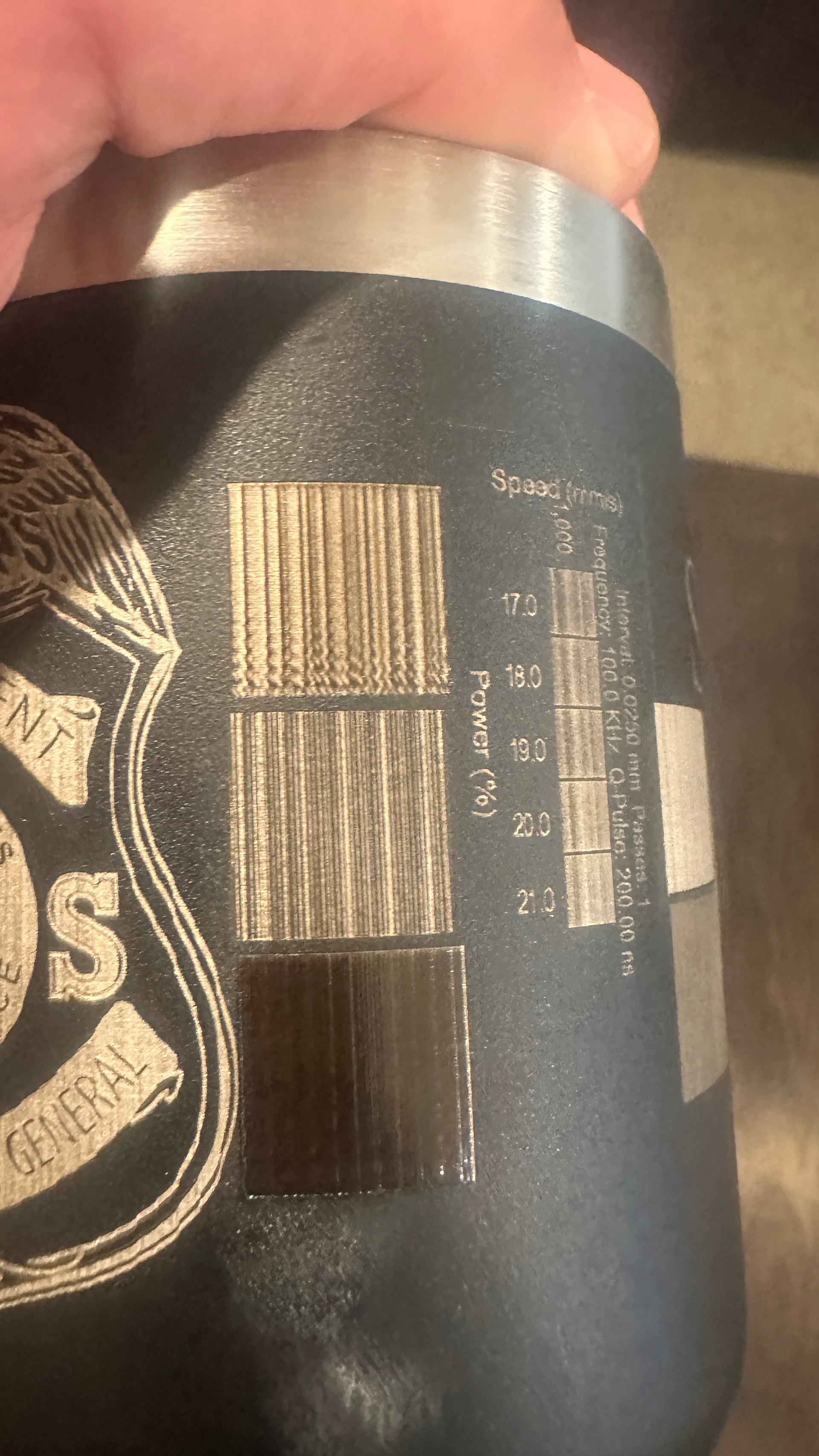
A 20 mm × 2 mm rectangle engraved with the exact same settings is dramatically smoother than a 20 mm × 20 mm square. The banding gets progressively worse as the engraved height increases.

  1. 45° scan angle improves the finish but doesn’t solve the issue.

The surface texture becomes smoother, but the periodic banding remains.

  1. LightBurn timing overrides are OFF.

Controller defaults are:

  • Laser On TC: -300
  • Laser Off TC: 100
  • End TC: 300
  • Polygon TC: 100

Things I’ve Already Ruled Out (I think):

  • Laser power
  • Frequency
  • Pulse width
  • Focus
  • Line interval
  • Scan angle
  • Number of passes
  • Split size
  • Overlap
  • Rotary motor speed
  • Rotary acceleration

What I’m Seeing:

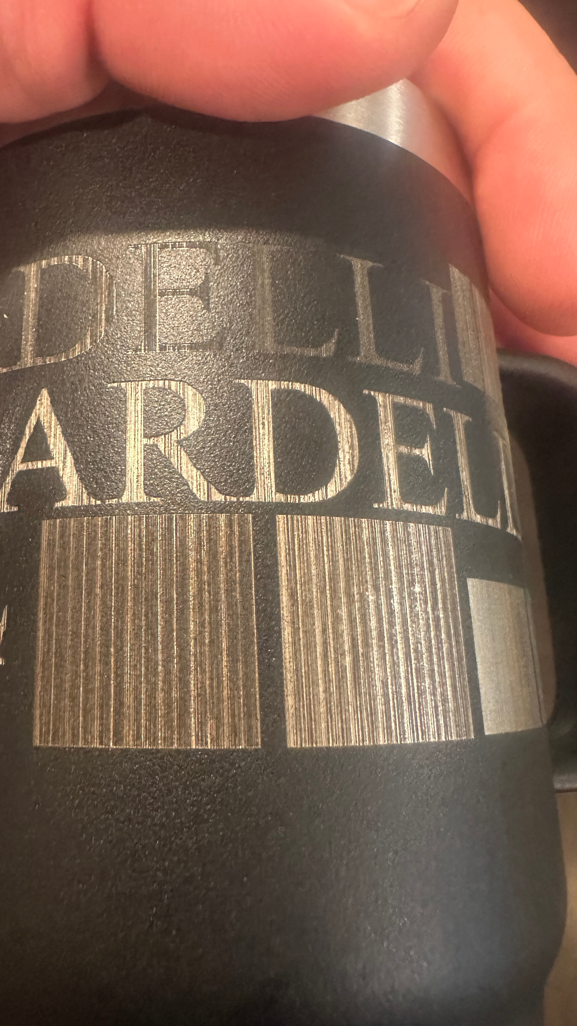
As the engraving becomes taller, very consistent horizontal bands develop.

The laser scans a strip, the rotary indexes, the laser scans another strip, and repeats. The effect almost looks cumulative.

I’ve attached photos of all my testing.

My Questions:

  1. Has anyone seen this behavior with a JCZ USB-Lite controller?
  2. Does this look like a LightBurn galvo rotary issue?
  3. Is there another rotary parameter I’m overlooking?
  4. Is it worth setting up EZCAD to see if the behavior changes?
  5. Does this resemble backlash, missed microsteps, or an issue with LightBurn’s split algorithm?

Any ideas would be greatly appreciated. I’m happy to run additional tests if someone has a theory.
Removing coatings and exposing shiny stainless on yeti tumblers is not easy with a fiber galvo. Experience factor: High.

More of a job for a UV galvo. But it can be done. For starters scan parallel to rotary axis. If possible get a non coated stainless tumbler to get things dialed in, one less variable. No cross hatch.

On lettering take advantage of “Run Whole Shapes” If your rotary is a good one your overlap should be as close to zero as possible.

Exact measurement is important. with overlap set to zero, try reducing your circumference a tiny bit at a time and observe results.

Try lowering your kHz 100 seems kind of high. A little out of focus (closer) to sync with the circumference reduction.

There are some fine tuning tips we have as well, but first you need to get a lot closer. If you have a crappy rotary or a crappy microstep driver you will have a lot more trouble of course.

@Albroswift is great with these, so take into consideration what he says.

I’d like to start with how you pick your interval. I’ve pretty important with most lasers, but fibers can show strange results, especially if things don’t match up correctly.

Generally speaking we use a starting interval that is very close to the machines spot size. In your case, I can’t really tell. If you are describing coverage, that’s not the same as focal length.

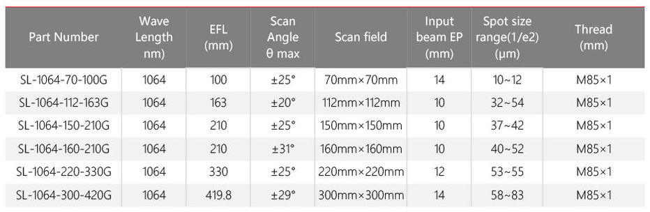
If you’re creating a 150mm area coverage, it’s likely you’re using an F210mm lens or nearly. As you can see, the spot size is relative to the focal length, not the coverage. Although a longer lens has more coverage but isn’t proportional enough to be used in calculations.

Going by this, your spot size is around 40 microns (0.40mm). If you scan at an interval of 0.020mm, you’re covering the same area twice. You skipped the area I though would be closest.

You machine has a range of 1kHz to 4000kHz, fixating on a single frequency or q-pulse (200ns) value, is causing you to ignore the best part of a MOPA type machine. There are only about 16 different pulse shapes.

Your source manual, but it’s still Chinglish. This is mine for a M60 M7 JPT source.

As in the manual, your most power is at 45kHz for a frequency.

Not sure what you mean here… The fibers pulse/s rate is it’s frequency, is that what you mean? There are no motors in these unless you have a motorized Z.

Actually you haven’t ruled out frequency or q-pulse duration (width). I never use scan angle with a rotary, too much spinning the rotary that isn’t necessary. I have used wobble for a thicker line.

When I do a materials test with the fiber, I give it a very wide range and I usually vary the speed and power, then speed, frequency and q-pulse.

If you’re used to other lasers, it’s likely the you are not used to a fiber. Most lasers are continuous mode, fiber and many other lasers are pulse machines. What makes a fiber really work it getting the frequency and q-pulse.

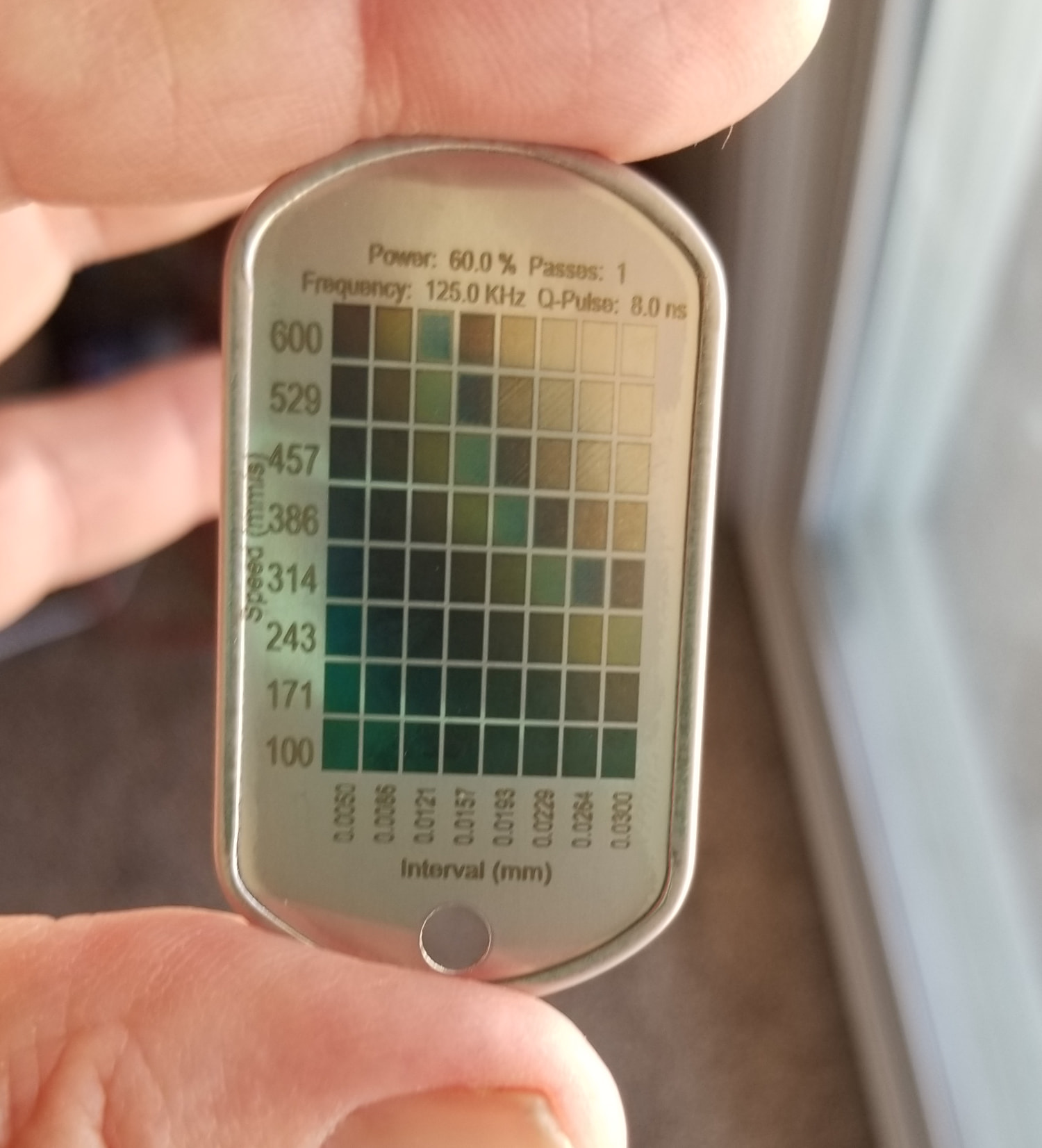
This is a stainless steel dog tag, a cheap one. I only varied the speed and interval. You can see the change in just an interval.


The machine will run jobs faster if it has a larger split size, as least it does on my v1.7 Split size is usually dependent on lens length. If you can use the lenses depth of focus (dof), then you can use a larger split size on a larger object.

If your object is the blue line, focus black line and green is the depth of focus. Above and below the black line is the complete dof.

Everything waits when the rotary has to move. Larger diameter larger available split size.

Make sense?

Probably left out a few things, maybe when I wake up… :man_shrugging:

:grinning_cat: